Project ZB-4
Four-band CW QRP transceiver by DL6ZB
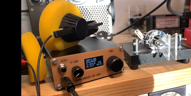
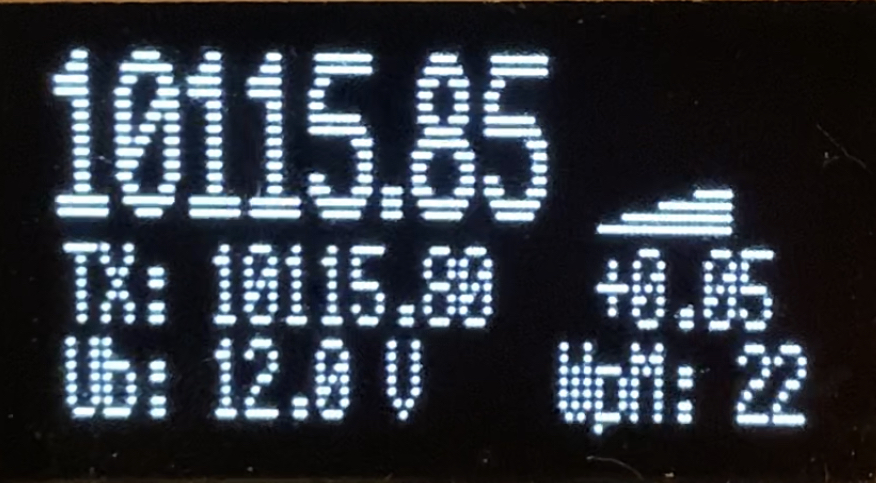
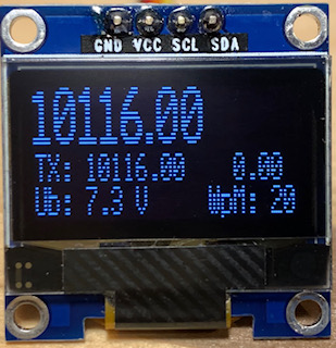
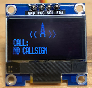
Here's a weekend project for the home builder.
| Band(s) | 80 / 60 / 40 / 30 m |
|---|---|
| Mode | CW, QSK |
| Output power | 5 W, MOSFET |
| Receiver | direct conversion, 74HC4066 mixer |
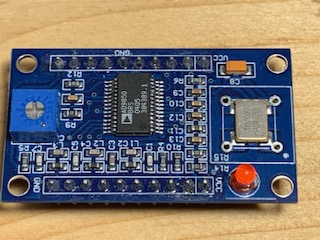
| VFO | AD9850 DDS module |
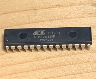
| Microcontroller | ATmega328P-PU, 20 MHz clock |
| Display | 0.96" SSD1306 I²C OLED, 128 × 64 |
| Firmware | V 1.0.12, hex files (download below) |
I'd like to introduce my latest homebrew project: a neat, easy-to-build four-band CW QRP transceiver. The design is based on a classic DC receiver and a class C transmitter.
The VFO is an Analog Devices AD9850 DDS module, which is the heart of this tiny multibander. These DDS modules are usually available for less than US$15 / €15 from AliExpress, Amazon, or eBay.
The AF amplifier following the 74HC4066 mixer consists of a pair of NPN BJTs forming the low-noise preamplifier, a single TL084 quad op-amp for amplification and filtering, and a JFET for RX/TX muting. In my opinion, this is about the minimum number of semiconductor components needed for a well-performing shortwave DC amateur radio receiver. Both sidebands are received, but I found that this isn't a real drawback.
A classic LM386 audio power amplifier drives a small loudspeaker or headphones. Be careful with the volume, because this DC receiver has no automatic gain control (AGC): strong signals can produce painfully loud audio in the headphones. To limit this, two anti-parallel diodes are connected to one of the TL084 amplifier stages.
The front-end mixer is made from a 74HC4066 CMOS switch. This mixer is so good that almost no additional filtering is required between the antenna and the mixer input. However, as a precaution, I added a 3 MHz high-pass filter to keep strong noise below the filter's cutoff frequency away from the receiver input.
Features
- AD9850 DDS generator module
- Microchip ATmega328P-PU, 16/20 MHz
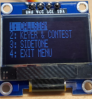
- Rotary encoder for frequency and menu
- 9600 baud RS-232 remote control, Kenwood protocol
- QSK with frequency shift and RX mute
- Microcontroller sidetone generator
- Automatic CQ call, also with CQ loop
- CQ loop contest mode
- Setup of your individual callsign for CQ
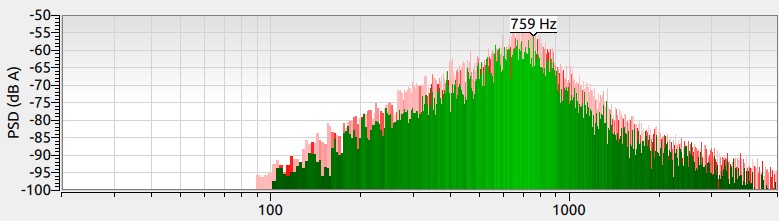
- Fixed CW filter, 700 Hz center frequency
- PC remote control, Kenwood TS-480 standard
- Receiver RIT for split-mode operation
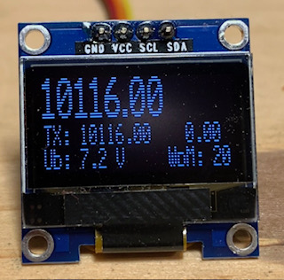
- Relative signal strength display
- Battery voltage display
- I²C OLED display, 128 × 64
- Smooth iambic keyer, 5 to 50 WPM
- Single-lever and straight key option
- Bug key simulation option
- Output power 5 watts, MOSFET
- Elliptic LPFs: 80 & 60 m and 40 & 30 m
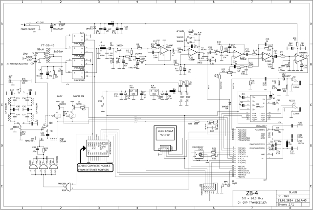
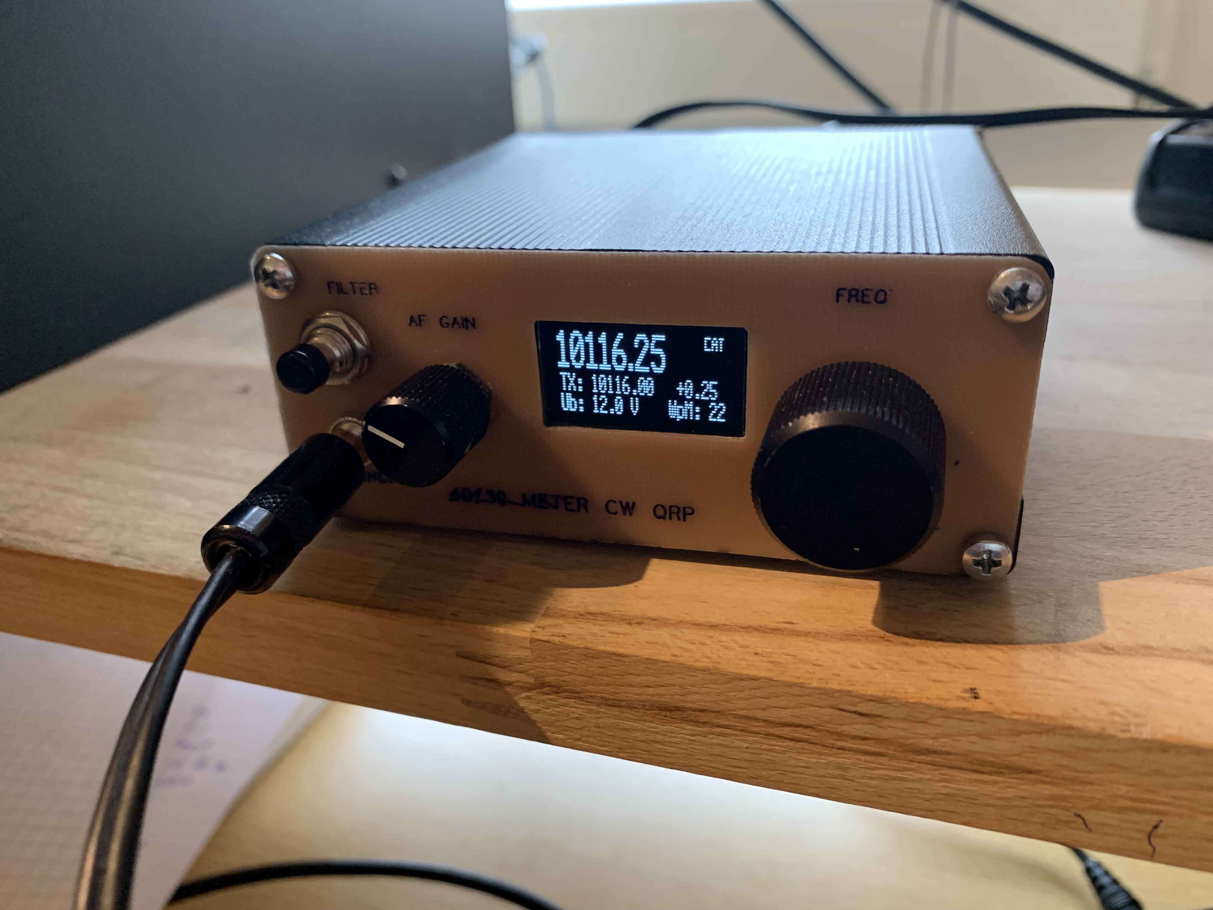
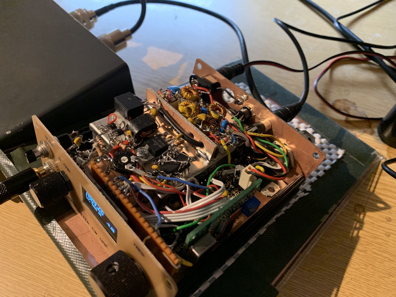
The receiver is housed in the tinplate enclosure, which is hidden beneath the transmitter and low-pass filters. The transmitter, with its output transistor, is mounted on top of the tinplate case. Behind it are the two low-pass filters for 80/60 and 40/30 meters. On the right side are the DDS and the microcontroller.
Alignment
Almost no alignment is necessary. The receiver's performance depends greatly on the setting of the DDS trimmer potentiometer. This trimmer sets the required 180-degree phase relationship of the two DDS output signals feeding the 74HC4066 mixer. An oscilloscope is a great help, but you can also adjust it for best reception with a small screwdriver.
AD9850 DDS Board: Entering Serial Programming Mode
By default, the AD9850 is in parallel mode, as set at the factory. However, as soon as the microcontroller has successfully sent the first data packet in serial mode to the AD9850 DDS (which can easily be checked with a monitor receiver), the DDS oscillator stays in serial mode as long as the RESET line is connected to GND. Be sure to check this!
The datasheet states that data lines D3 and D4 must be connected to VCC and data line D2 to GND, but apparently this statement in the datasheet is not correct. The AD9850 apparently enters serial mode automatically once it has successfully received serial data in the correct sequence.
Some pre-assembled AD9850 boards available online do not have the RESET line connected to GND. If in doubt, check the RESET pin's connection to GND on your board.
RF Low-Pass Filters
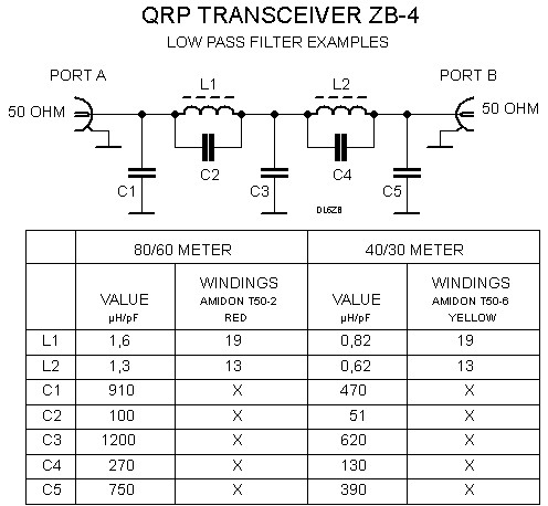
These filters have an input and output impedance of 50 ohms. I recommend Cauer (elliptic) filters for sufficient harmonic suppression. The table in the low-pass filter diagram above gives example values.
In the photos, you can see that I do not use the red-coded cores (T-50-2). Of course, you can use them as listed in the table. T37 cores should work without heating up too much. However, there is still some room for experimentation here. Please e-mail me if you have any suggestions for improvement. The values in the table are just examples.
AF Bandpass Filter
I like it when the CW signal I'm interested in is boosted, but the activity around that frequency remains slightly audible. If you prefer a sharper CW filter, there's plenty of room for experimentation.
The picture below shows the frequency response measured with a noise generator and plotted by SDR software.
Note: The dB scale here is only relative.
Push Buttons
The transceiver has two push buttons: <ENC> and <WPM>.
- <ENC> is the rotary encoder's push button.
- <WPM> is the multi-function WPM button.
| Button | Short press | Long press |
|---|---|---|
| <ENC> | TX zero beat | Menu |
| <WPM> | CW speed (words per minute) | Auto CQ |
| <ENC> + <WPM> | QSO mode: auto CQ loop, CQ 10 times, 10-second spacing | Contest mode: auto CQ loop, 10 times, 2-second spacing |
Table of functions for both push buttons on the front panel.
Auto CQ
This transceiver has an auto-CQ feature. To use it, enter your callsign in the corresponding menu item.
Auto CQ can be interrupted by pressing either push button, <WPM> or <ENC>.
The auto-CQ feature remains disabled until a valid amateur radio callsign has been entered.
PC Remote Control
The transceiver partially emulates the Kenwood TS-480 PC remote control. The RS-232 speed is 9600 baud, 8N1. I have tested the remote control with several PC ham radio programs, such as CQRLOG and DXLab. However, I haven't implemented every Kenwood command, so I can't guarantee that it works with every available PC program.
Download: Firmware ZIP file
The clock speed is set to 20 MHz.
Latest version: March 31, 2023, V 1.0.12
Upload the hex files to the ATmega328P (Arduino environment) with the XLoader software: https://github.com/binaryupdates/xLoader
Please send me an e-mail (dl6zb@dl6zb.de) if you have any questions about the project.
Legal Notice
Software provided on my website dl6zb.de is freeware with the following restrictions: You may download and use the software for your projects and copy and distribute the download link. You may redistribute the software, but you may not modify the source code or the compiled software without my written permission. You may not modify the copyright notice. Commercial use of any kind is prohibited.
THIS SOFTWARE IS PROVIDED BY ME, ROLF HEINE, AS THE COPYRIGHT HOLDER AND CONTRIBUTOR "AS IS," AND ANY EXPRESS OR IMPLIED WARRANTIES, INCLUDING, BUT NOT LIMITED TO, THE IMPLIED WARRANTIES OF MERCHANTABILITY AND FITNESS FOR A PARTICULAR PURPOSE, ARE DISCLAIMED. IN NO EVENT SHALL I OR CONTRIBUTORS BE LIABLE FOR ANY DIRECT, INDIRECT, INCIDENTAL, SPECIAL, EXEMPLARY, OR CONSEQUENTIAL DAMAGES (INCLUDING, BUT NOT LIMITED TO, PROCUREMENT OF SUBSTITUTE GOODS OR SERVICES; LOSS OF USE, DATA, OR PROFITS; OR BUSINESS INTERRUPTION) HOWEVER CAUSED AND ON ANY THEORY OF LIABILITY, WHETHER IN CONTRACT, STRICT LIABILITY, OR TORT (INCLUDING NEGLIGENCE OR OTHERWISE) ARISING IN ANY WAY OUT OF THE USE OF THIS SOFTWARE, EVEN IF ADVISED OF THE POSSIBILITY OF SUCH DAMAGE.
Copyright © Rolf Heine, DL6ZB, Kirchenäcker 6, 84048 Mainburg, Germany.