Homemade Transceiver Project
20/80 m CW QSK QRP Transceiver
October 2020, DL6ZB
| Band(s) | 20 m and 80 m |
|---|---|
| Mode | CW, QSK (diode RX/TX switching) |
| Output power | about 3 W into 50 ohms |
| Receiver | single conversion, 9 MHz IF |
| Construction | Manhattan style |
| Schematic | PDF download (see below) |
This is a 20/80 m CW QRP transceiver using the "imaging" technique.
The "imaging" transceiver technique, widely used by homebrewers in the 1960s and '70s, usually uses a 9 MHz IF. A 5.0–5.5 MHz VFO results in 3.5 MHz and 14 MHz input/output at the same time. The desired band is selected with a band filter. The design of the receiver's IF circuit was inspired by VA3IUL.
The output power of the described transceiver is about 3 watts into a 50-ohm load.
The design goal was to keep it simple, using mostly junk-box parts and as many BJTs and simple op-amps as possible.
Most of today's homemade projects use microcontrollers and more or less sophisticated frequency engines. No doubt these projects are of great value for learning about modern RF technologies.
However, there are still a lot of homebrewers looking for more traditional projects. If you're one of them, this project may be for you.
This project will be updated from time to time. It is built Manhattan-style to allow quick changes.
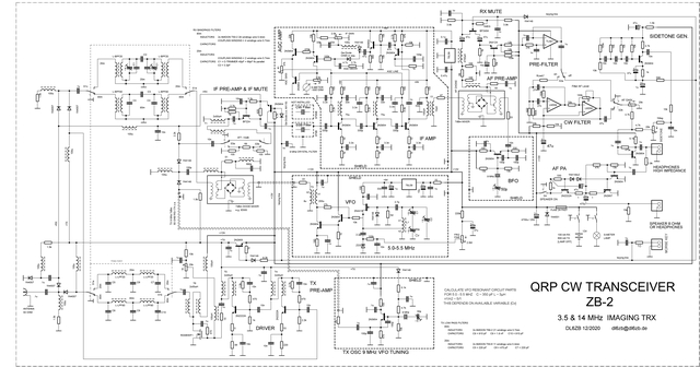
The receiver is a single-conversion type with an IF of 9 MHz. A 2.7 kHz KVG XF-9B SSB crystal filter from the junk box was used here. Any cheap CB radio SSB crystal filter or a ladder filter will do the job. Two commercial ring mixers are used. I have also successfully tried simple ring mixers made of 1N4148 diodes plus a ferrite toroid (3 × 50 µH).
The main problem with this single-conversion IF design is keeping the 9 MHz BFO emissions away from the IF amplifier. This is done by proper shielding.
The receiver has a 2.4 kHz bandwidth. I added a simple but surprisingly effective 300 Hz bandwidth op-amp AF filter. A better choice would certainly be a CW crystal IF filter (e.g., XF-9NB). However, I didn't have one in my junk box. The op-amp filter does the job.
A small speaker or high-impedance headphones may be used. Low-impedance headphones require either an additional AF stage or connection to the loudspeaker output. I will add a low-impedance headphone amplifier stage later. Meanwhile, the speaker output can be used with low-impedance headphones.
An early design had relay RX/TX switching. It was too noisy for me, so I changed it to a diode QSK switching circuit. The schematic shows the new diode RX/TX switching design for QSK operation. The transceiver is still built "Manhattan-style" ("dead-bug style"), which allows modifications at any time.
The current design (PDF) is also available.
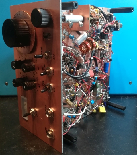
Front view
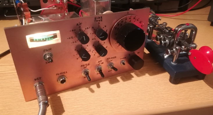
Top view
- VFO with a 1:36 planetary gear
- IF and AGC amplifier (open case)
- S-meter
- Crystal filter
- AF amplifier
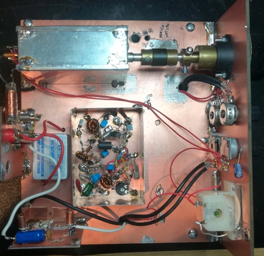
Bottom view
- Front panel
- RF TX driver and power amplifiers
- AF preamplifier and AF filter
- 9 MHz RX and TX crystal oscillators
- Bandpass and TX low-pass filters
- T/R switching