Weekend Project
30-Meter BJT QRP Transceiver (ZB-1 / ABACUS-1)
Rolf Heine, DL6ZB
Five transistors, standard parts, one weekend: the ZB-1 is a QSK CW transceiver for the 30-meter band with a direct-conversion receiver and about 1.5 watts of RF output. All components except the crystals are standard and readily available.
| Build time | A weekend ("Weekend Project") |
|---|---|
| Active devices | 5 BJTs (2× 2N2222A, 2N3553, 2× 2N3904) |
| Band(s) | 30 m (approx. 10,108–10,122 kHz) |
| Mode | CW, QSK |
| Output power | approx. 1.5 W |
| Supply | 12 V (per schematic) |
| Firmware / code | None needed (no microcontroller) |
How it started
On a rainy Saturday afternoon, I was searching through my collection of spare parts for a suitable connector to make a cable. During this search, I stumbled upon a small bag of 10,111 kHz crystals.
Inspired by this discovery, I decided to put these crystals to use by designing a minimalist QRP transceiver for the 30-meter band.
The result is a dedicated 30-meter single-band transceiver with an RF output of approximately 1.5 watts and a tuning range of approximately 10,108 to 10,122 kHz.
The design
The primary design objective was to build a QSK transceiver using just five BJTs and a homemade diode ring mixer. With its direct-conversion receiver, this transceiver covers a frequency range of at least 10 kHz by pulling the oscillator crystals.
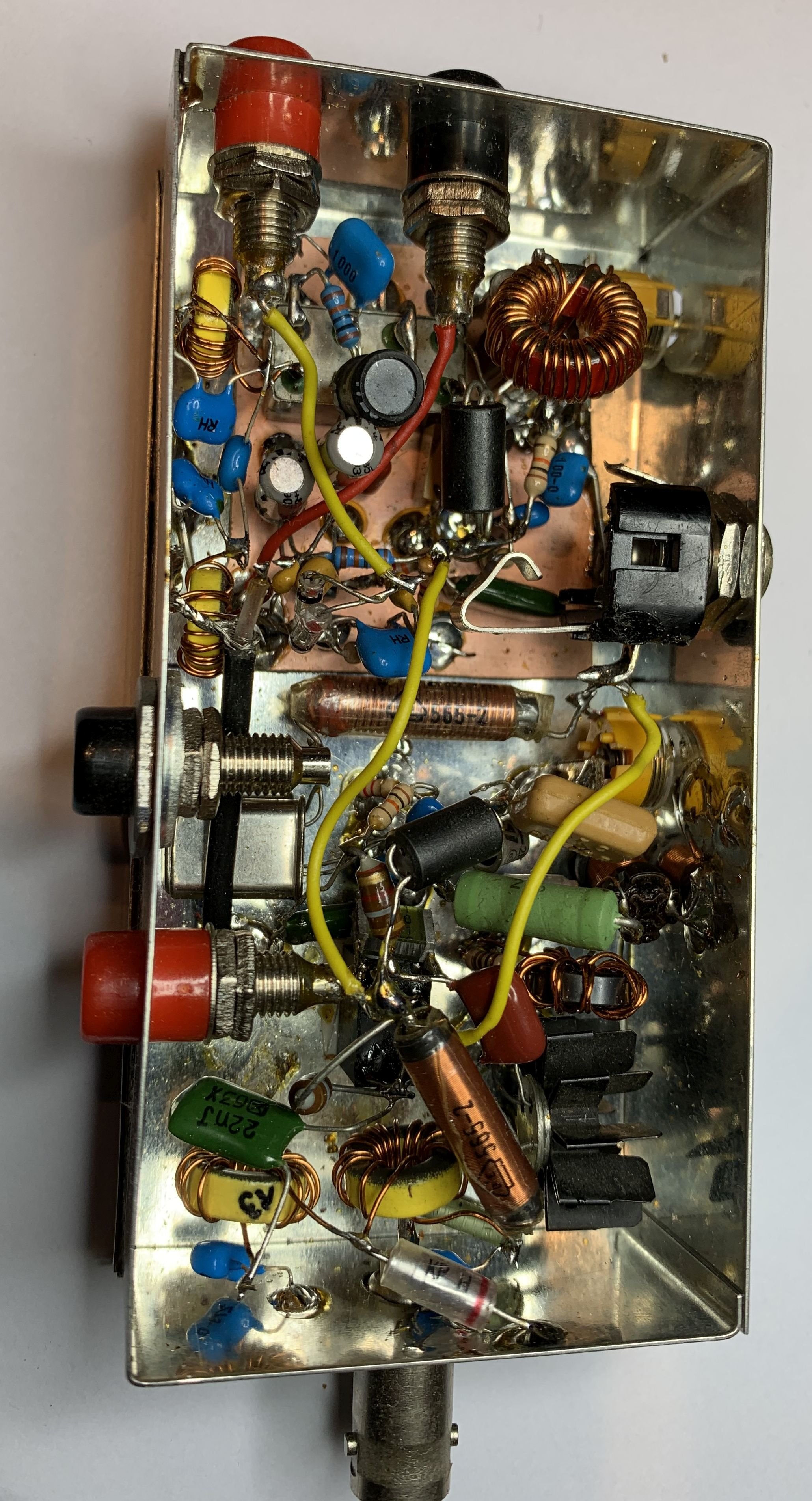
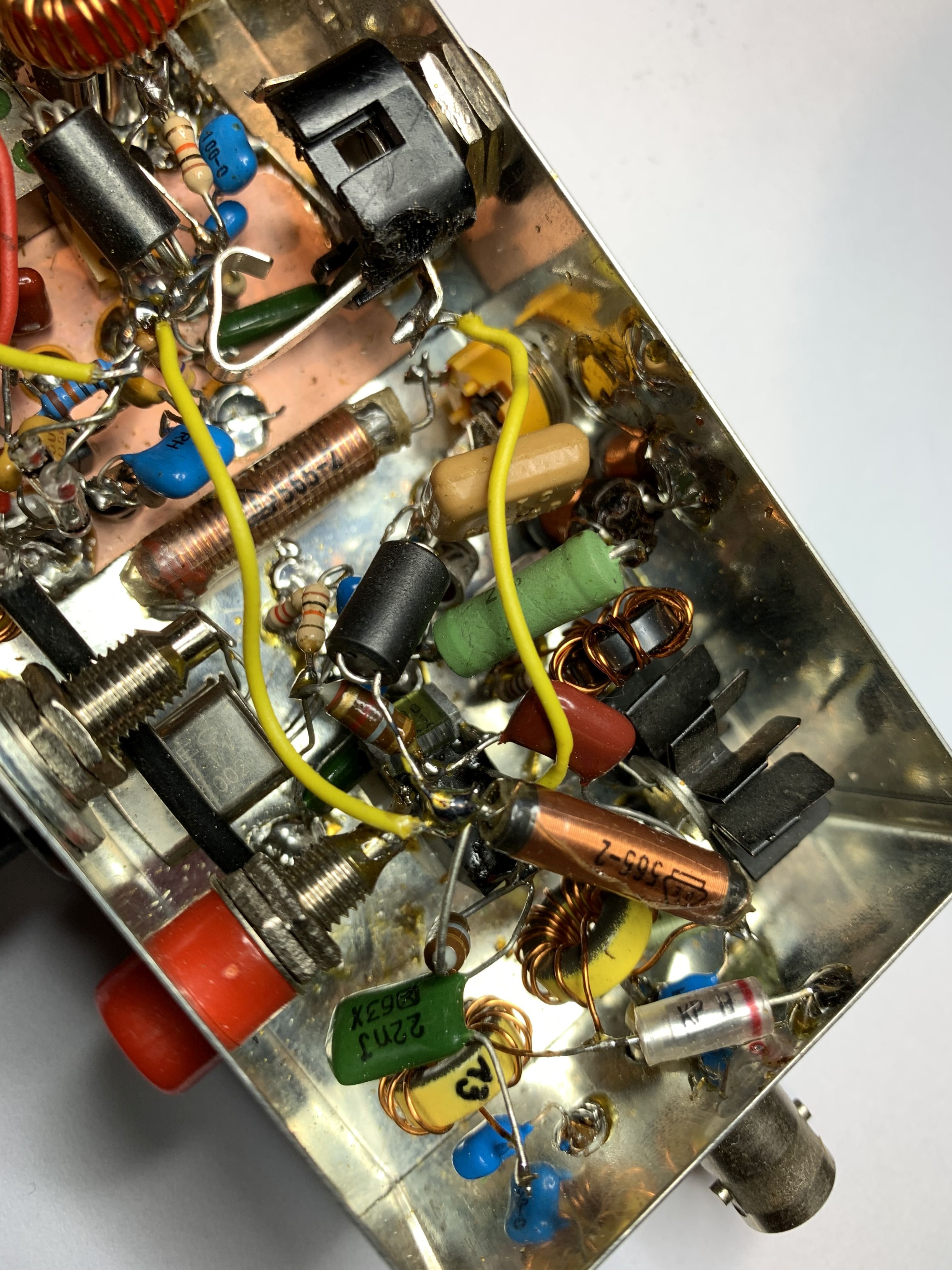
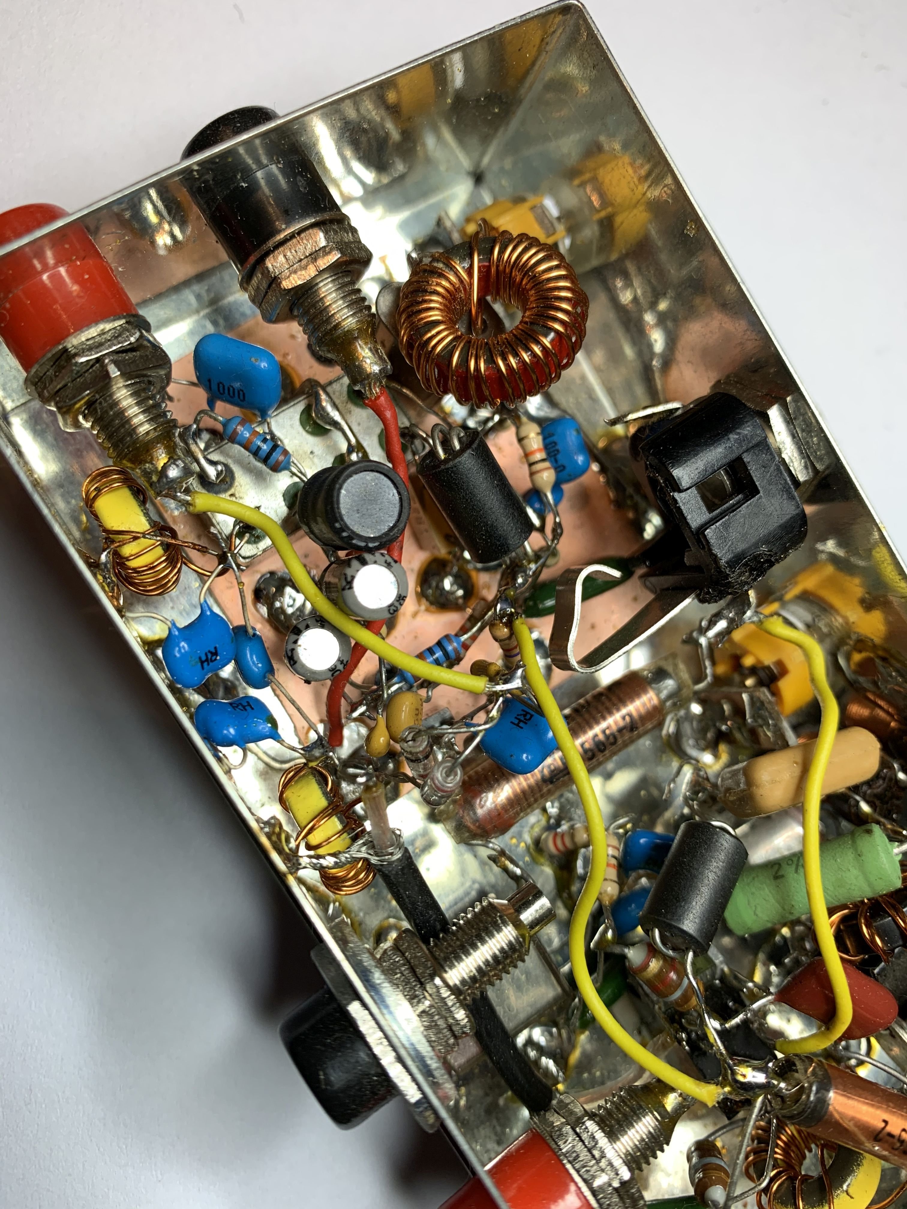
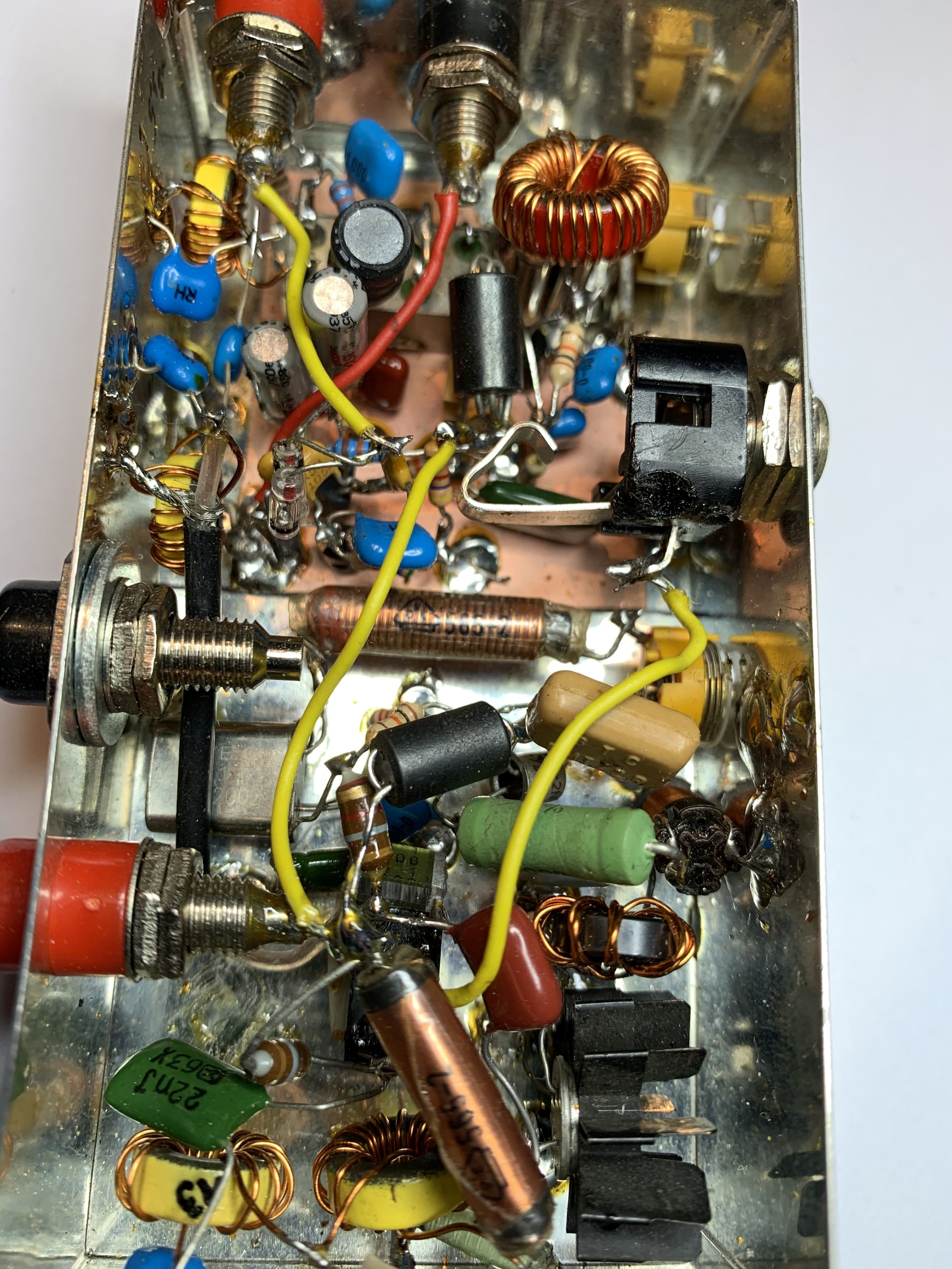
All components used are standard and readily available, with the exception of the crystals, which came from my parts collection. The version shown features an IE-500 diode ring mixer.
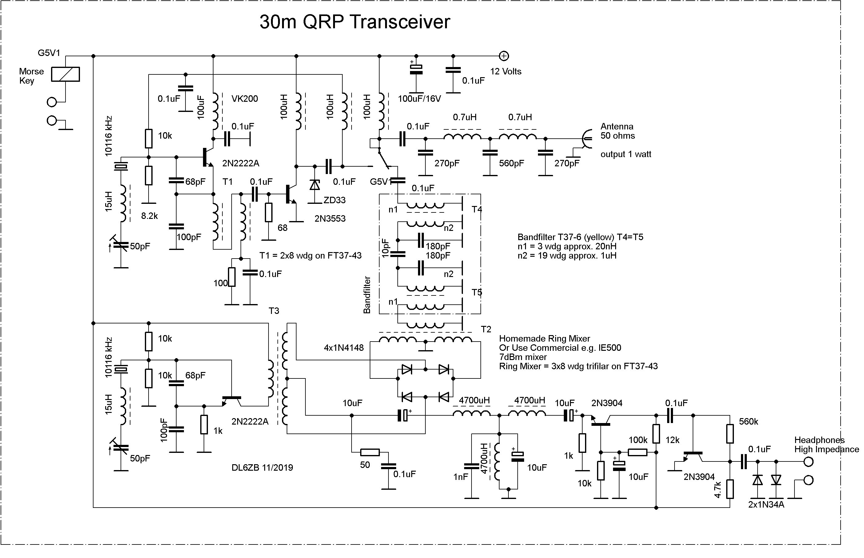
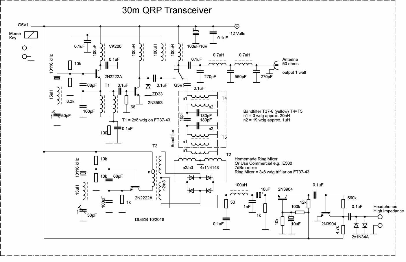
This transceiver has two oscillators, one for receiving and one for transmitting, which allows the transmit frequency to be offset. This frequency shift during transmission generates a sidetone in the receiver section. The high isolation of the RX/TX antenna relay ensures a satisfactory AF sidetone level.
Receiver audio
The AF amplifier requires a high-impedance load at its output; hence, 2000-ohm headphones were used. Anti-parallel germanium diodes at the AF output are a good choice for limiting the audio to a comfortable level when strong signals appear at the antenna input.
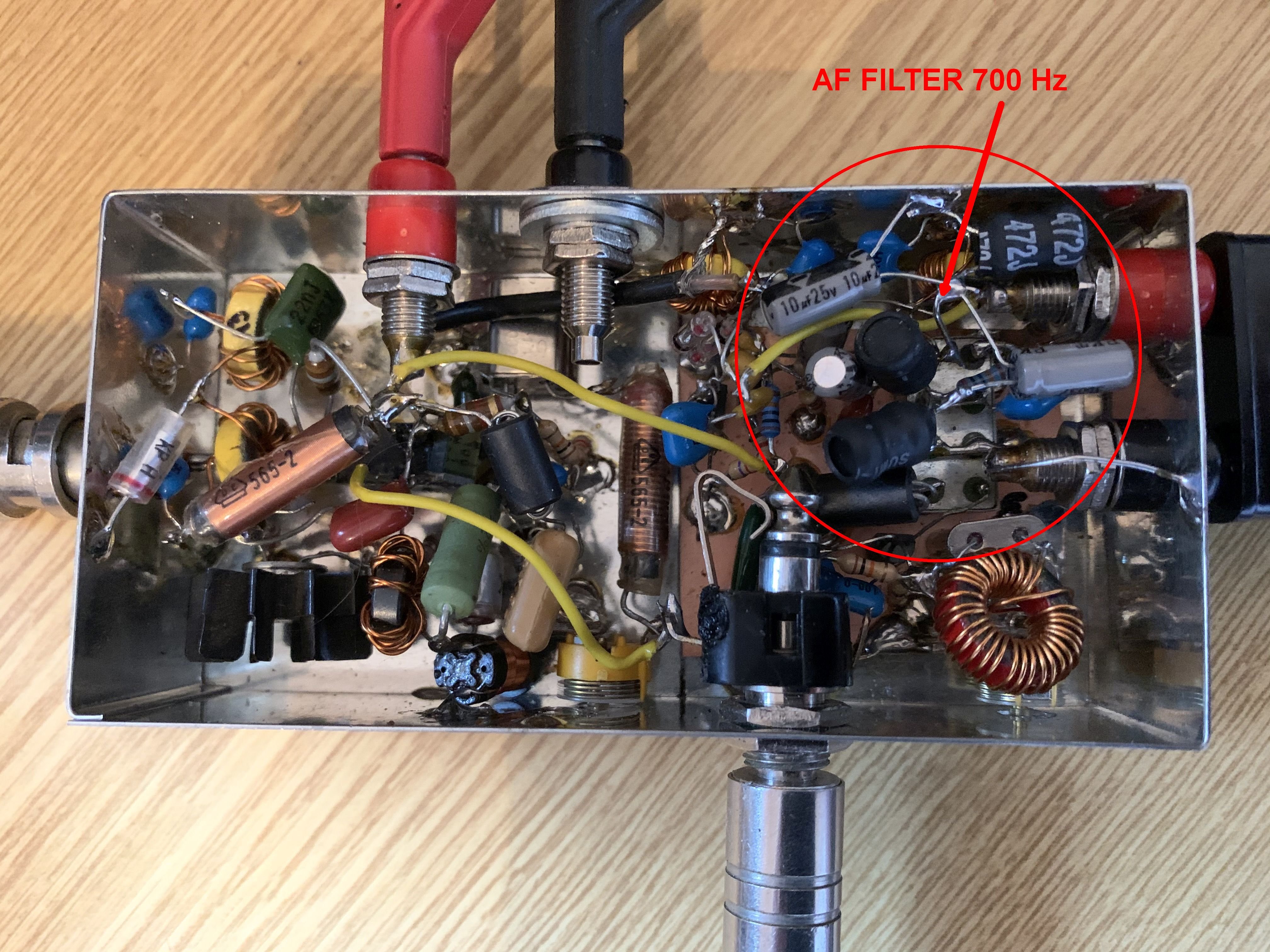
Optional 700 Hz AF filter
An alternative version includes an additional AF filter with a frequency peak of around 700 Hz. The 4700 µH inductors used are FASTRON 07P-472J-51.
Transmitter and PA protection
A ZD33 Zener diode is placed at the collector of the 2N3553 output transistor to protect it against damage in case of an antenna mismatch or a sudden antenna disconnection during transmission. This prevents immediate damage to the output transistor if it has no load during transmission.
While the 2N3553 transistor may be hard to obtain, any other low-power RF transistor rated at 2 watts, such as the 2N3866 or even a BD135, can serve as a substitute. BS170 FETs may also be worth a try.
Key parts at a glance
- Two pullable crystals for the 30-meter band (one RX and one TX oscillator)
- Diode ring mixer: homemade, or a commercial IE-500
- Output transistor 2N3553 (substitutes: 2N3866, BD135; BS170 FETs may be worth a try) with a ZD33 protection Zener diode
- RX/TX antenna relay with high isolation (G5V1 in the schematic)
- High-impedance headphones (2000 ohms)
- Optional AF filter: FASTRON 07P-472J-51 inductors (4700 µH)
- Enclosure: Schubert case no. 6 (111 × 55 × 30 mm)
Enclosure
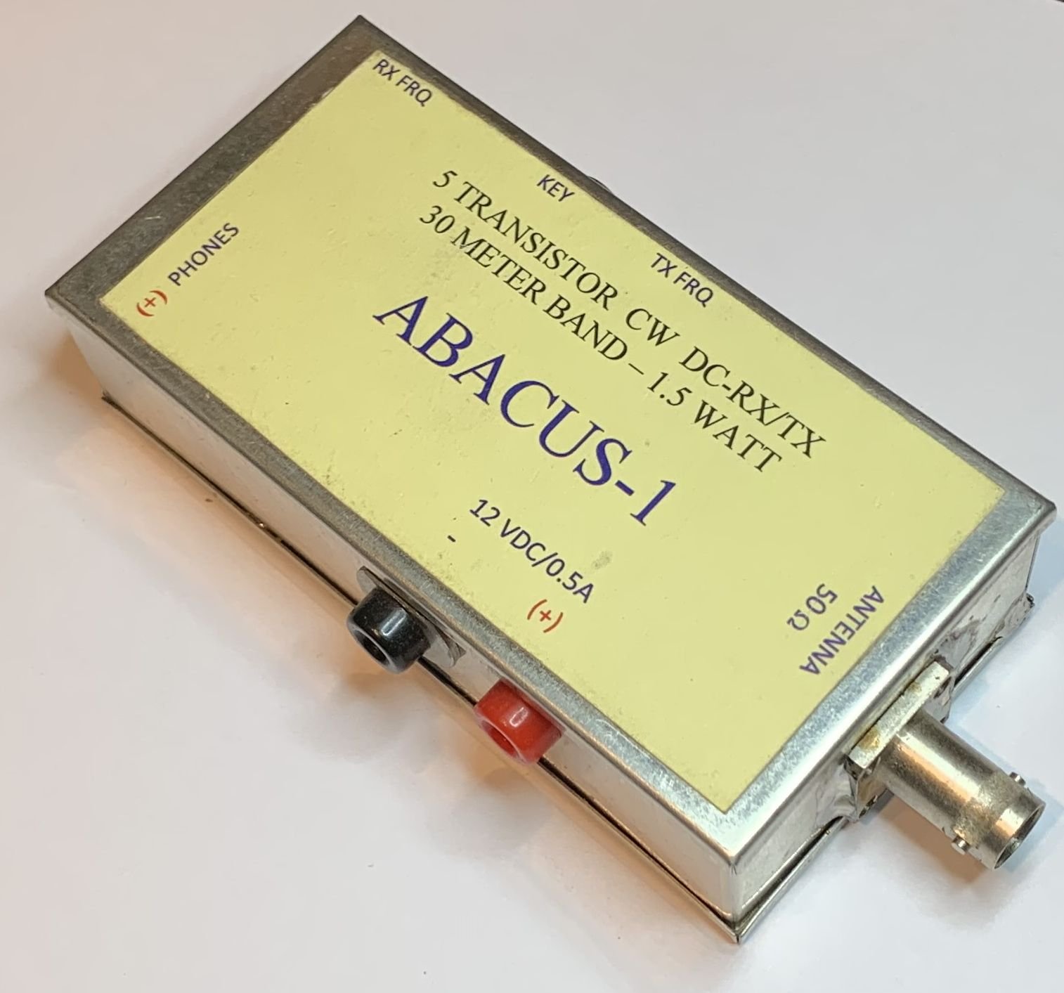
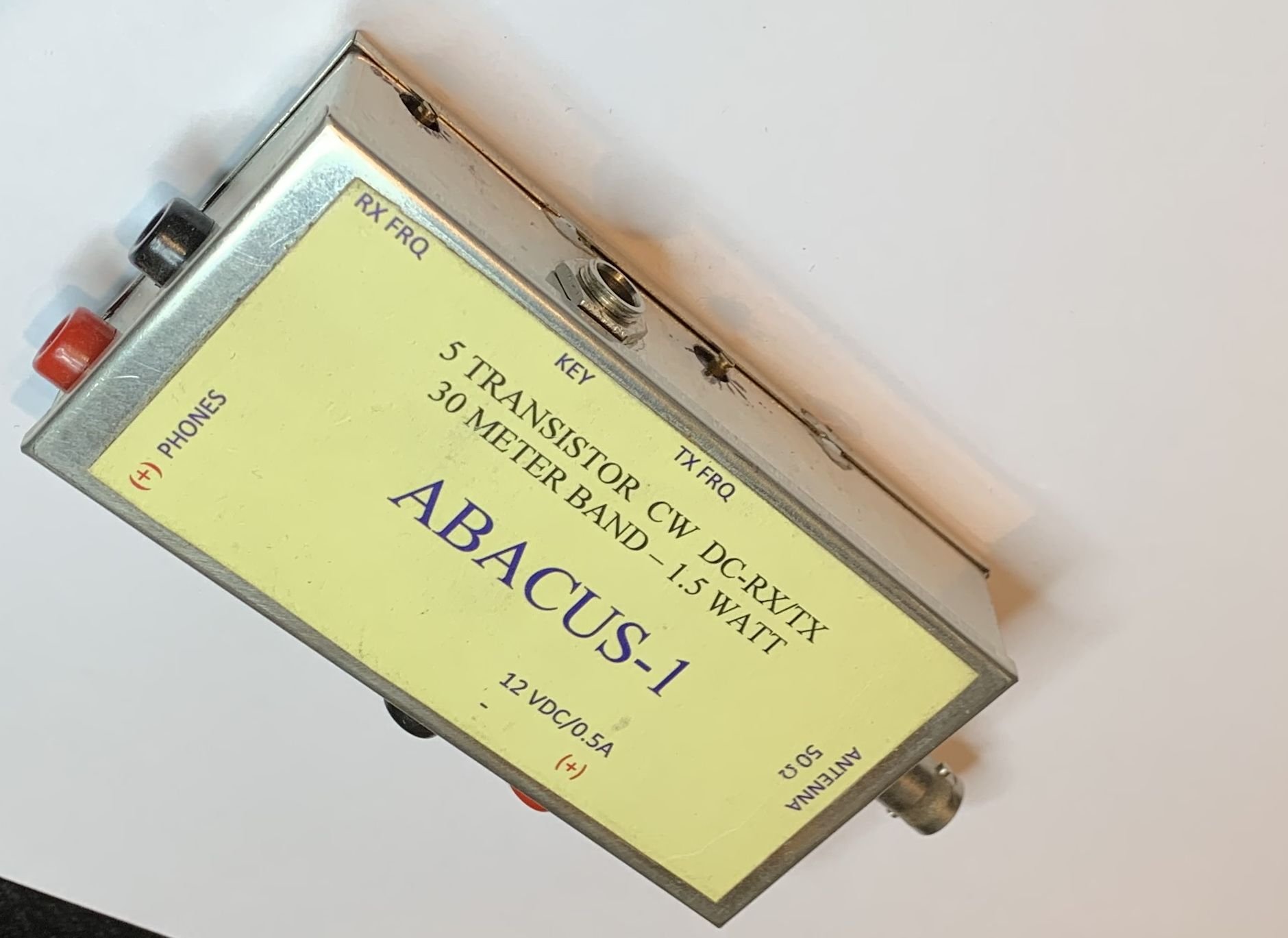
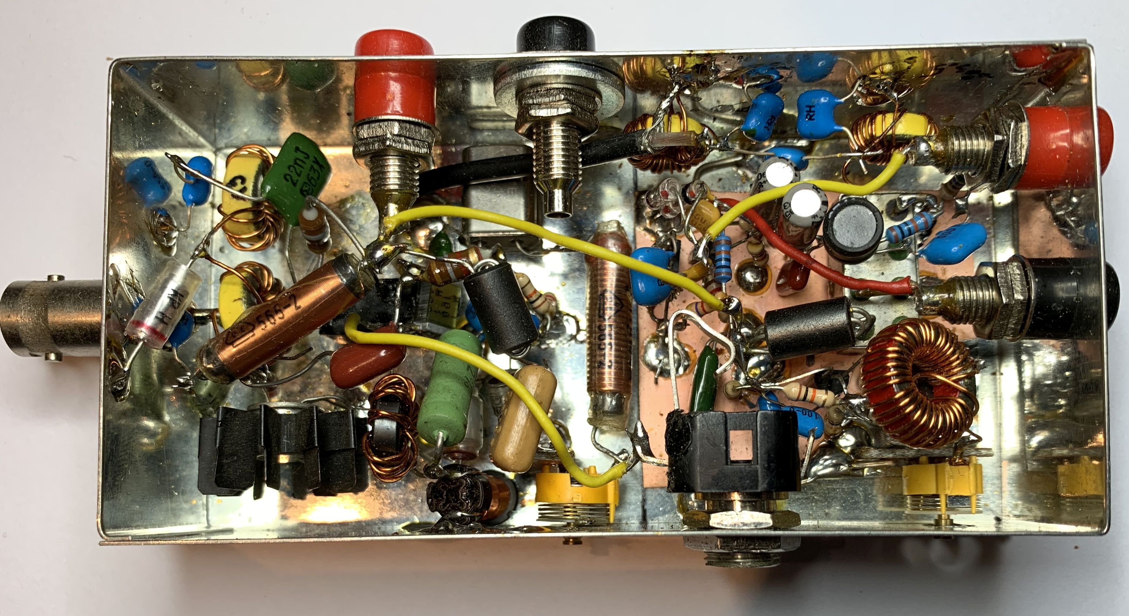
The enclosure is from Otto Schubert GmbH, Germany: case no. 6, measuring 111 × 55 × 30 mm (L × W × H). More information here: schubert-gehaeuse.de – Weißblechgehäuse
Schematics
Click on the schematics and pictures for higher resolution.
Photos
Your turn!
Five transistors, a handful of standard parts, and a free weekend – that's all it takes to put your own homebrew rig on 30 meters. Built one? Send me a photo and tell me about your first QSO, your substitutions, or any problems you ran into: dl6zb@dl6zb.de. I'm always happy to hear from fellow builders.
73, Rolf, DL6ZB