Weekend Project
Memory CW Keyer Upgrades Your Classic Transceiver or Homebrew Rig
Project by DL6ZB
Download the user manual (PDF)Edition 2.1, October 2026, for firmware 2.1.0 · 31 pages · 1.2 MB
Considering upgrading your classic or DIY rig? This project could be just what you're looking for.
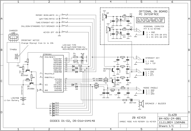
ZB Keyer Schematic
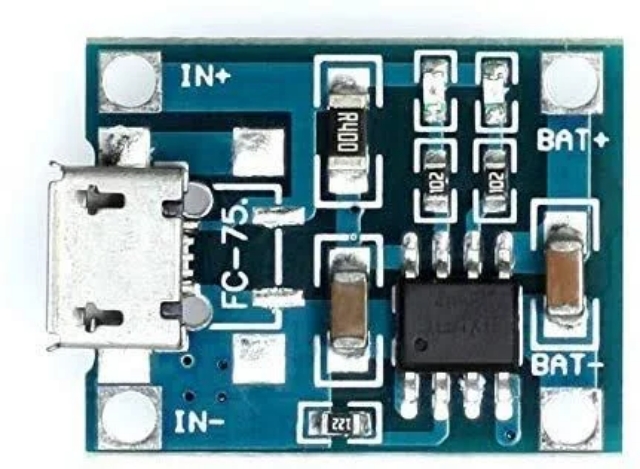
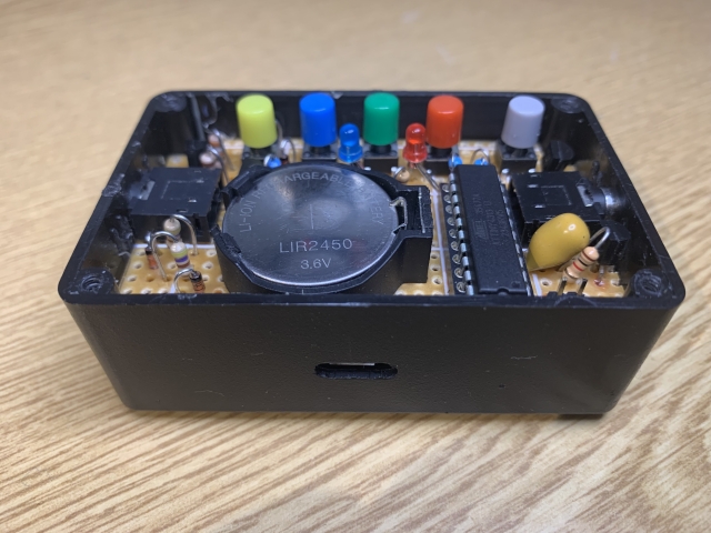
Set the charge current with the programming resistor Rprog (marked "122"). By default, it is 1.2 kΩ, which gives a 1 A charge current; replace it with 22 kΩ for a suitable charge current of about 60 mA (2-hour charge).
Software Download (ATtiny4313 Version)
The software for the ZB Keyer is available in hex format as public domain, according to the terms and conditions published on this website. Check this website for updates.
The software is available as a zipped hex file here: ZB-KEYER.ZIP (latest update: November 11, 2024, version 2.1.0)
User manual: Download the user manual (PDF) – Edition 2.1, October 2026, for firmware 2.1.0 · 31 pages · 1.2 MB
See the information at the bottom of this page on how to program the microcontroller.
User Information – ZB Keyer Manual
Rolf Heine, DL6ZB
Version 2.0.9
Microcontroller: Microchip® ATtiny4313
Last firmware update: April 9, 2024
1. Features
- Dash/dot keyer for single- and dual-lever paddles
- Iambic squeeze mode A / mode B option
- Auto CQ
- Auto CQ loop
- Callsign memory
- Standard text memory
- CW speed and sidetone adjustment
- CW and PTT line keying
- Straight key option
- PTT delay options: QSK / 0.6 second / 1.2 seconds
- Speaker output
- Dash/dot ratio adjustment
- Option for RTS/DTR CW and PTT connection to a personal computer's serial (RS-232) port
- Auto power-off (sleep mode)
2. Technical Data
| Parameter | Value |
|---|---|
| Voltage | 2.5 to 5.5 V |
| Max. supply voltage | 6 V (absolute maximum!) |
| Current (approx.) | 0.05 µA (sleep mode) – 0.8 mA (operation) – 9 mA (transmit) |
| Operating temperature | −10 to +70 °C / 15 to 160 °F |
| Max. keyed CW/PTT | 35 V / 0.2 A |
| Speed | 5 to 50 WPM |
| Memory | approx. 35 characters |
| Microcontroller | Microchip® ATtiny4313 |
| System clock | 1 MHz |
3. LED Functions
- Red LED flashing/continuous: memory functions
- Blue LED flashing/continuous: special functions
4. Push-Button Functions (Short/Long Press)
The keyer is controlled by:
- 4 push buttons
- the dash/dot lever(s) of a connected single- or dual-lever paddle
Push-button definitions:
- Button 1: memory read/write button
- Button 2: WPM/sidetone/ratio button
- Button 3: tune/straight key button
- Button 4: CQ/callsign/standard text button
- Button 5: power-off button
Buttons 1 to 4 – short press (main functions):
- Button 1 short: memory read mode – sends the callsign or standard text; stop with the paddle or button 1
- Button 2 short: WPM – adjust with the dash/dot paddles; press button 2 again to finish
- Button 3 short: tune / straight key
- Button 4 short: send CQ – press once more for the CQ loop (10×); stop with the paddle or button 1
- Button 5: shuts off the keyer
Buttons 1 to 4 – long press (approx. > 0.5 seconds):
- Button 1 long: memory write mode – enter a callsign or standard text of up to 35 characters
- Button 2 long: sidetone adjustment with the paddles
- Button 3 long: tune / straight key
- Button 4 long: sends "QRL?"
Sequence for two-button procedures:
Press the 1st button → release the 1st button → press the 2nd button → release the 2nd button.
Buttons 1 to 4 – two-button additional functions:
- Button 1 long + button 2: PTT delay = 0 (QSK mode)
- Button 1 long + button 3: PTT delay = 500 milliseconds
- Button 1 long + button 4: PTT delay = 1 second
- Button 2 short + button 1: dash/dot ratio adjustment (see section 6 below)
- Button 2 short + button 3: toggles dash/dot memory; LED/speaker signal: A = off, B = on
- Button 2 short + button 4: toggles the speaker on/off
Stored parameters:
All adjustable parameters remain in memory after the ZB Keyer is switched off and are reloaded when it is switched on again.
Caution: Individually programmed parameters will be deleted if a full reset is performed. The ZB Keyer parameters are then set to their default values.
5. Memory Mode Procedure in Detail
Pressing button 1 for more than approx. 0.5 seconds switches the ZB Keyer into memory write mode. While in memory mode, the ZB Keyer's memory LED (red) is on.
The ZB Keyer then waits until either:
- the paddle levers are operated to start loading the memory, or
- button 1 is pressed once more to exit memory mode without changing the memory.
Up to about 35 characters can be entered as long as the red memory LED is on. When the memory is full, the red memory LED turns off automatically.
Remark: If the paddle is left untouched and button 1 is pressed again, memory mode is exited without any change, and the ZB Keyer returns to CW mode, leaving all previously stored information in memory. This helps if button 1 was pressed unintentionally.
Memory write mode ends when:
- the paddle is released for more than approx. 1 second, or
- button 1 is pressed.
Memory read mode is started by pressing:
- button 1 – transmits the standard text / callsign only
- button 4 – transmits the auto-CQ text with the stored callsign
Example: CQ CQ CQ CQ CQ DE DL6ZB DL6ZB DL6ZB K
CQ loop mode:
The ZB Keyer enters CQ loop mode if button 4 is pressed once more while a CQ call is being sent. In CQ loop mode, the CQ call is repeated approx. every 10 seconds for 10 rounds.
Immediate stop of transmission:
You can stop any transmission at any time by operating the paddle or pressing button 1.
Deleting the memory:
The memory is overwritten by loading a new callsign or new standard text according to the memory mode procedure. The memory and all parameters are deleted by a full reset (see the full reset procedure).
6. Dash/Dot Ratio Adjustment Procedure
- Press button 2 (WPM): the blue LED flashes dots.
- Press button 1 (memory): the blue LED flashes dots, the red LED flashes dashes.
- Operate the paddle levers to adjust the ratio: the dash lever increases the ratio, the dot lever decreases it.
- Remark: Press button 2 once more at this point to restore the standard 1:3 dot/dash ratio.
- Press button 1 (memory) to end the adjustment and store the ratio in memory.
7. Personal Computer Connection
PC software and the ZB Keyer can be used in parallel by connecting the CW and PTT keying lines of the PC's serial port to the ZB Keyer's "TRANSCEIVER" connector, pins 2 and 3. Many widely used ham radio programs use the RTS or DTR lines of the RS-232 (serial) port for this purpose. The DTR and RTS behavior can be selected in the ham radio software settings.
In addition to everyday CW QSO operation, this means that PC software – whether contest software or logbook software with a CW keyer option – can be used as a standard-text keyer, while the ZB Keyer can be used in parallel to send additional Morse code manually when necessary.
Caution: Use only pins 2 and 3 of the ZB Keyer's TRANSCEIVER connector to connect the RTS/DTR keying lines of a PC's serial port. RS-232 serial port lines must not be connected directly to the ZB Keyer's straight key input connector, since RS-232 voltage levels exceed the ZB Keyer's maximum ratings. Serious damage to the microcontroller will occur if an RS-232 keying line is connected to the ZB Keyer's straight key connector.
9. Sleep Mode
The auto power-down feature switches the keyer into sleep mode after 15 minutes without any operation, so you don't need to switch it off manually to save battery life. In sleep mode, the current consumption drops to 0.1 µA.
The keyer wakes up when any keyer function is operated or the paddle or straight key is used.
Sleep mode can be activated manually by pressing button 5.
10. Full Reset Procedure
- Press button 1.
- Press button 2 while keeping button 1 pressed.
- The memory LED turns on.
- Wait until the memory LED turns off.
- Release the buttons.
- Done.
- All adjustable parameters are set to their default values.
- The callsign (or standard text) is erased from memory.
Check your transmitter's PTT voltage before connecting it to the ZB Keyer; otherwise, excessive voltages may seriously damage your transmitter or the keyer. See the technical data for more details about voltages and currents.
How to Program the ZB Keyer's Microcontroller
Option 1: Probably the Easiest Way to Burn the Firmware (Windows/Linux)
If your computer has a real, physical RS-232 port, this may be your choice. Search Google for more details about the PonyProg hardware and software; there's quite a lot of information available. It's an easy way to upload hex files.
Option 2: USBasp (Windows/Linux)
- Get an AVR ISP programmer, e.g., a USBasp, for about 10 bucks.
- Install Atmel Studio (Microchip Studio) or AVRDUDE on your computer. Both are free.
- Configure the software for the programmer/port and the microcontroller type.
- Upload the hex file to the microcontroller via the ISP port.
- Done.
Option 3: The Longest but Possibly the Safest Route (Linux Only)
- Get an ATmega328P Arduino board. A $6 Chinese clone worked for me.
- Install the Arduino IDE on your computer.
- Go to File/Preferences.
- Add this to "Additional Boards Manager URLs":
https://drazzy.com/package_drazzy.com_index.json - Click OK.
- Go to Tools/Board/Boards Manager and search for "attiny".
- Install "ATTinyCore by Spence Konde".
- Select the board and microcontroller: Tools/Board/ATTinyCore/ATtiny2313(a)/4313 (No Bootloader).
- Open the sketch File/Examples/ArduinoISP/ArduinoISP.
- Compile and upload the sketch to the Arduino.
- Close the Arduino IDE and disconnect the Arduino from USB.
- Install AVRDUDE:
sudo apt-get install avrdude - Important: At this point, connect a 10 µF capacitor on the Arduino board from RESET to GND.
The Arduino has now been turned into an ISP programmer.
The next step is wiring the Arduino to the ATtiny4313 for programming:
| Arduino | ATtiny4313 |
|---|---|
| D13 | Pin 19 (SCK) |
| D12 | Pin 18 (MISO) |
| D11 | Pin 17 (MOSI) |
| D10 | Pin 1 (RESET) |
| +5 V | Pin 20 (VCC) |
| GND | Pin 10 (GND) |
The ATtiny4313 is programmed by entering the command below in a Linux terminal window. Replace path_to_hex_file.hex with the path to your keyer hex file. Check the USB port: the Arduino Uno usually appears as /dev/ttyACM0, but it may be /dev/ttyUSBx instead.
avrdude -c arduino -p t4313 -P /dev/ttyACM0 -b 19200 -e -U flash:w:"path_to_hex_file.hex":i
For experts: you can use AVRDUDESS for more convenient programming instead of the command line.
Please send bug reports, comments, or questions to: dl6zb@dl6zb.de
Special thanks to Volker Herrmann (DL8WIG) for testing and useful comments.
Learn more about my hardware and software projects, and find legal information, on my website.