SSB Exciter with IF Clipper for QRP
DL6ZB, Rolf Heine
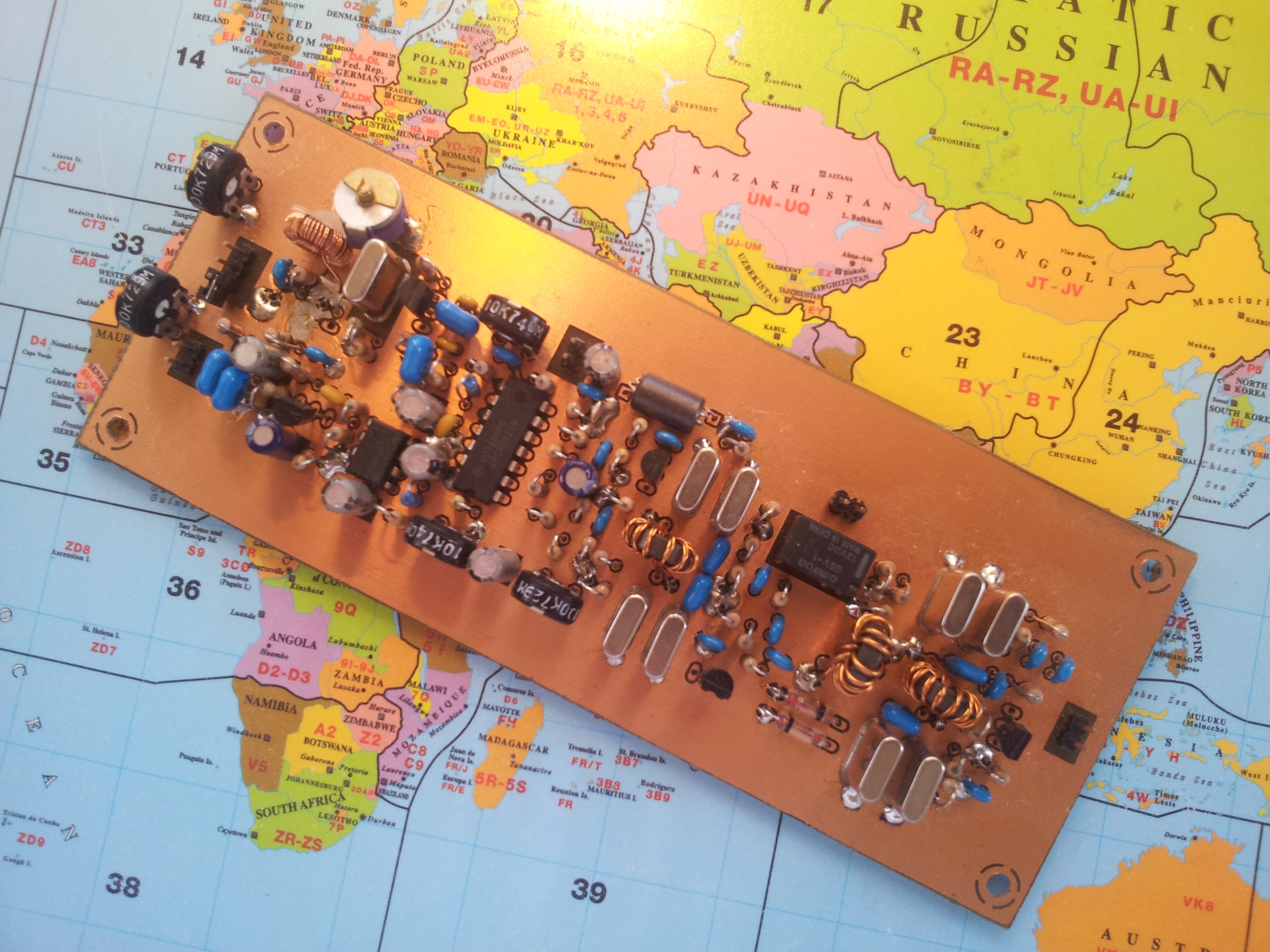
This is a description of a simple but effective 10.7 MHz single-sideband exciter with a built-in IF clipper. By changing the crystals, the concept can also be used for other IFs (e.g., 8 or 9 MHz).
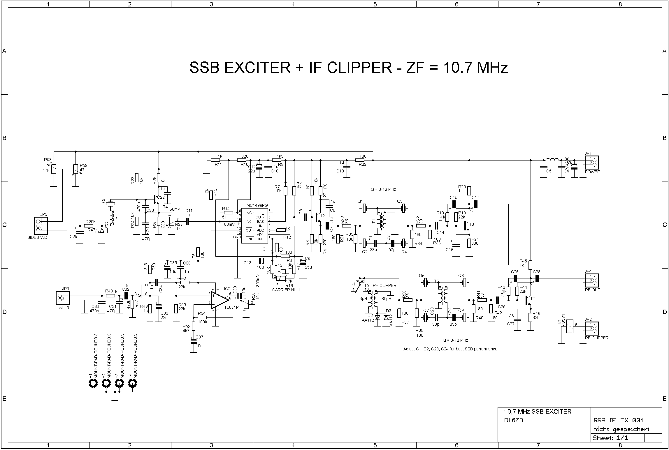
I have developed a special 50-ohm SSB (USB/LSB) crystal filter for this exciter. It is a so-called bridge design. Bridge filters are more suitable for SSB generation than ladder filters, because they can be tuned very easily without changing the impedance significantly. Just change the 33 pF capacitors to change the bandwidth of the filters. These filters can also be used in receiver IF stages. For higher filter orders, just cascade them. The bandwidth depends only on the value of the capacitors (see C1/C2).
The higher the value, the narrower the bandwidth. While staying within a VSWR of 2.5:1 (50 ohms), the bandwidth of these filters can be tuned from 6000 Hz down to 300 Hz. The sideband is changed by tuning the carrier oscillator crystal. The crystals don't have to be selected or tuned. However, I recommend using crystals of the same type (and manufacturer).
The switchable built-in IF clipper is a well-known, simple but effective diode clipper. It consists of germanium diodes and a step-up transformer. It was first described by Wes Hayward, W7ZOI. The IF clipper is followed by a second crystal filter, which provides a clean SSB output signal.
In theory, a clipper offers a 6 dB improvement in readability. This can be a big help for QRP. I use this exciter in my 160/80/40 m QRP SSB transceiver with good results.
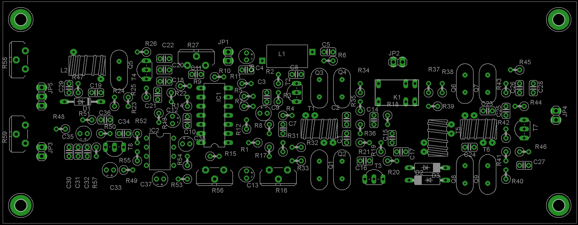
"SSB EXCITER 10,7.brd" is an EAGLE CAD file. A free (limited) version of the EAGLE PCB layout software is available from CadSoft; search for the free version of EAGLE.
The bottom layer is the routed layer; the top layer is just ground.
Try this link for the CAD software: https://www.autodesk.com/products/eagle/free-download
Click here for the 10.7 MHz SSB exciter PCB layout file.
Update
I would like to pass on some of the experiences of people who have built this SSB exciter.
The exciter is apparently easy to build and works well. However, the attenuators at the inputs and outputs of the crystal filters seem to attenuate too much, so the clipper does not work at full effectiveness.
I recommend omitting the attenuators at the input and output of the first crystal filter, which is just ahead of the balanced modulator. However, you should check the frequency response of the first crystal filter after removing the attenuators.
Removing the attenuators will make the clipper much more effective. In addition, I recommend using only germanium diodes or small Schottky diodes for the clipper.
Circuit Diagram
Click on the picture for a large-scale view.
Component Placement
Click on the picture for a large-scale view.