Single-Transistor Receiver and Transmitter Design
Rolf Heine, DL6ZB
Weekend Project: Single-Transistor Receiver – Regenerative Receiver for the 30 m Band
A 10-part "DX receiver"
After successfully building a single-transistor transmitter for 30 m, my next idea was to try a simple 30 m regenerative receiver with the best possible performance.
This receiver is surprisingly sensitive. Its performance is far better than I had expected. When I connected the receiver to the antenna for the first time, I could hardly believe what I heard! With just one transistor, this little thing was able to hear everything – loud and clear. Listen to an audio file here: audion.mp3
A word about frequency stability: the receiver frequency depends on all parts of the circuit, even a swinging wire antenna and the antenna tuner (matchbox), because all of them affect the frequency of the regenerative detector. This is the price of the extreme simplicity of this kind of receiver. Stability and performance can be improved significantly by adding a buffer preamplifier, at the expense of a more complex circuit. If a preamplifier stage is used, the regenerative stage must be shielded from the front end.
Circuit Diagram
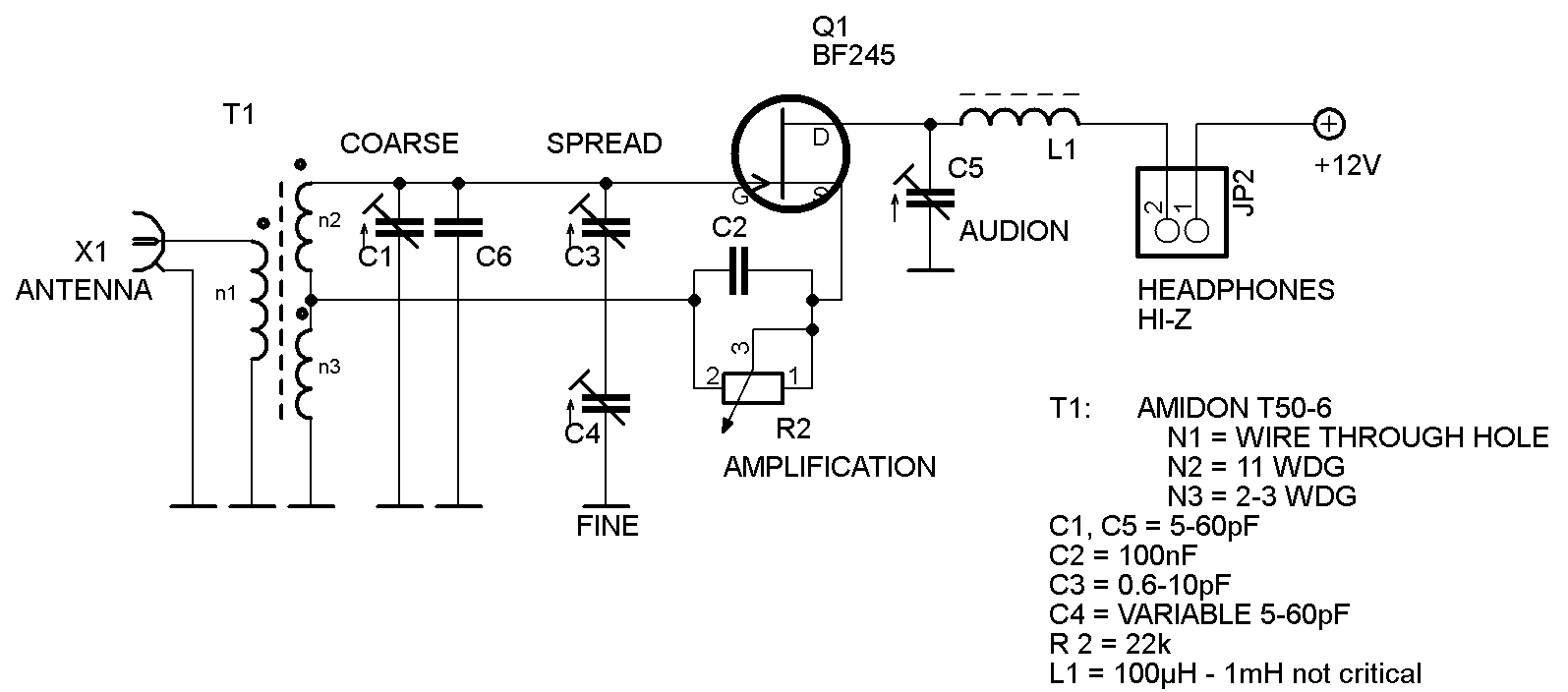
The circuit diagram shows the complete regenerative receiver schematic. The tickler (feedback) capacitor is set to about 30 pF. The variable resistor R2 is adjusted so that the receiver draws a current of about 150 µA. A frequency counter is very useful for aligning the circuit, although a broadband receiver used to find the receive frequency will do as well.
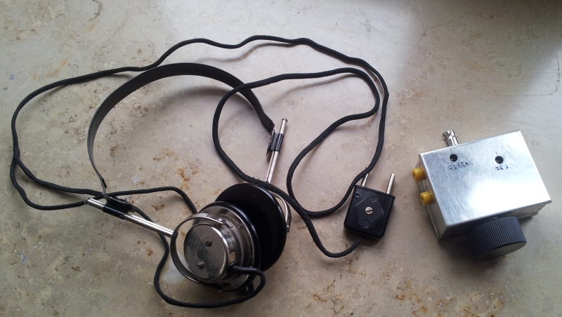
It is very important (!) to use high-impedance (~2–4 kΩ) headphones; otherwise, the circuit won't work. If you don't have high-impedance headphones, use a small AF transformer with a suitable impedance ratio. I use very sensitive, ancient 4 kΩ headphones that I found on eBay. In version 2, the variable resistor R2 has been replaced by a fixed 10 kΩ resistor.
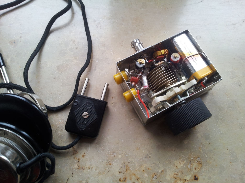
The receiver runs very well on an ordinary 9 V battery (type 6LR61). With its current draw of 150 µA, an alkaline battery lasts for up to 3,000 hours.
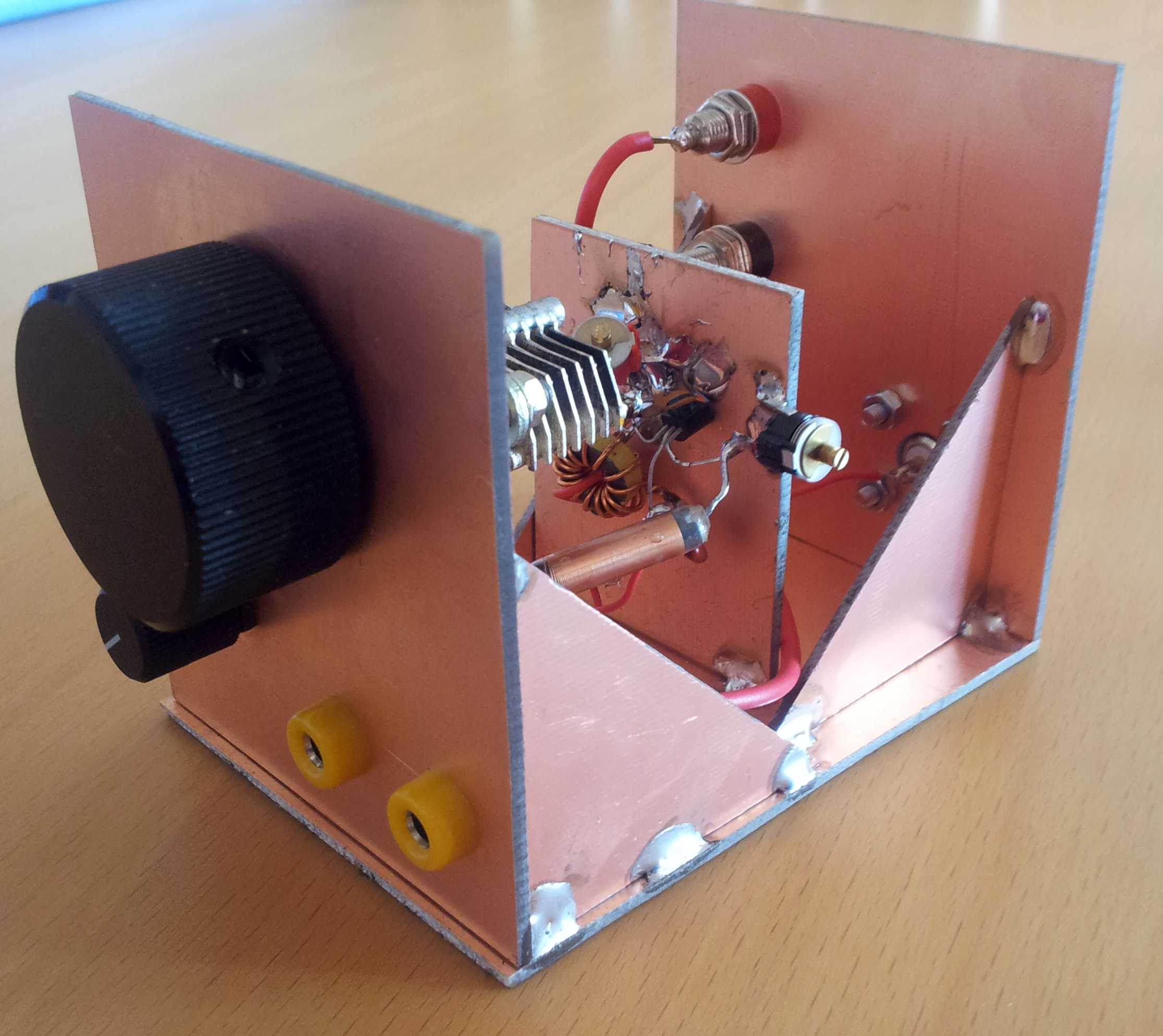
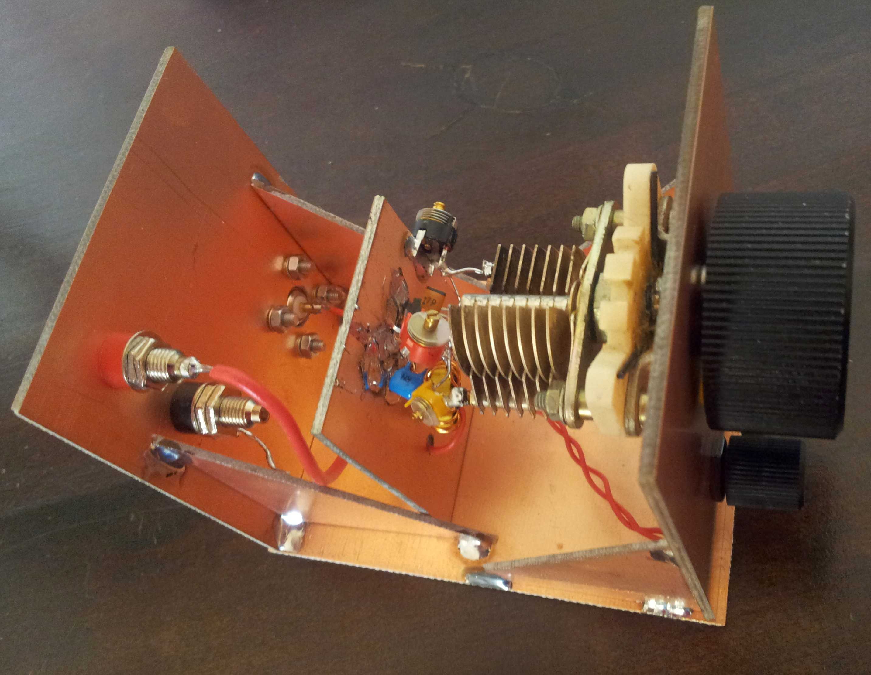
Single-transistor regenerative receiver
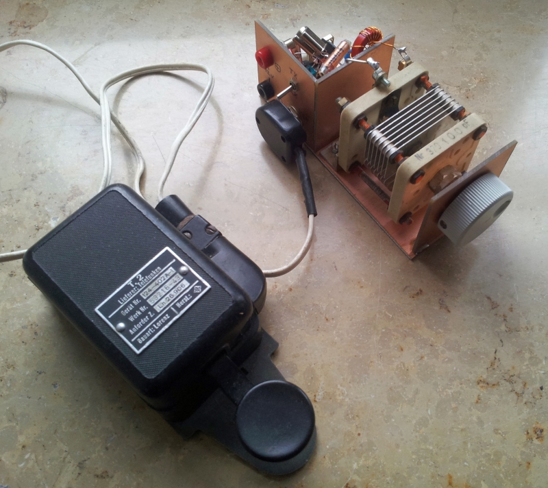
Weekend Project: 30 m QRPP Single-Transistor CW Transmitter
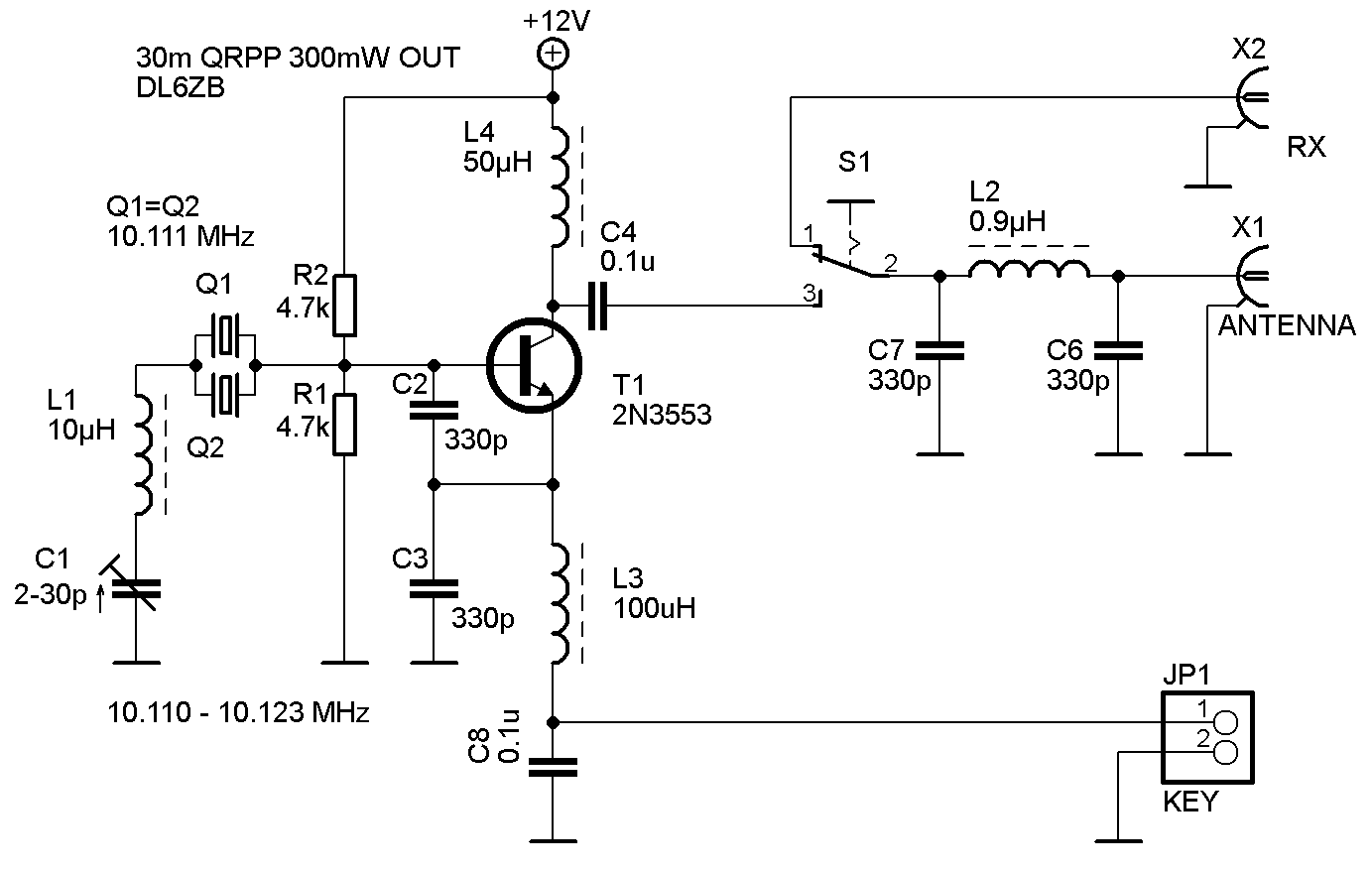
Our local electronics dealer recently offered 10.111 MHz crystals (now sold out). Add a few parts around one…
The output is approx. 300–400 mW. The two-crystal version allows a wider tuning range. (The Reverse Beacon Network map with the spots, originally shown here, is no longer available.)
Even W3LPL, at a distance of 4,200.2 mi (6,759.6 km), heard the 300 mW signal on 10,114.2 kHz from Germany with an SNR of 7 to 9 dB. This corresponds to 14 mi/mW, or 22.5 km/mW!
The decoupling at the collector is essential to prevent TX chirp. This transmitter produces a clean, chirp-free signal.
I used a 12 V battery as the power supply and, as the antenna, a 2 × 30 m random-wire inverted V, 25 m above ground.
Here are the first three QSOs made with the 300 mW QRPP transmitter:
| Band | Call | Country | Mode | Name | RST sent | RST rcvd | Date | Time |
|---|---|---|---|---|---|---|---|---|
| 30 m | F5LBG | F | CW | Bernard | 579 | 579 | 01-Dec-2012 | 11:27 |
| 30 m | ON4MB | ON | CW | Walter | 419 | 599 | 01-Dec-2012 | 14:29 |
| 30 m | OH3HTR | OH | CW | Kari | 539 | 589 | 01-Dec-2012 | 15:02 |