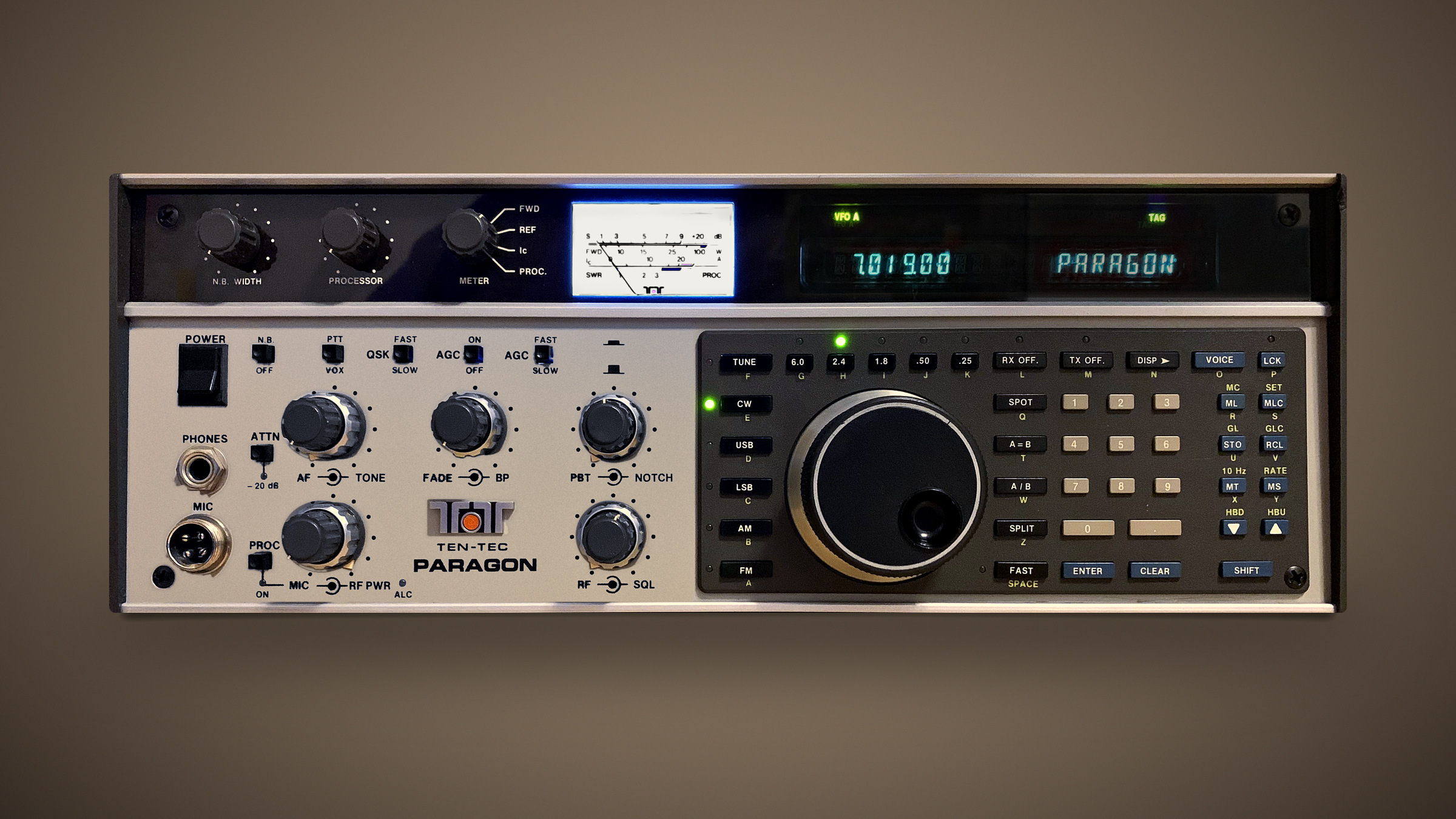
Firmware Adaptation for the TEN-TEC Paragon 585
Rolf Heine, DL6ZB
Version ZB V1.1 – tested on the radio. Feedback welcome.
| Version | ZB V1.1 |
|---|---|
| Radio | TEN-TEC Paragon 585 only (not 586) |
| Based on | Original TEN-TEC firmware V3.9 |
| CAT | CI-V, emulates Icom IC-718 (address 5E), 4800 baud 8N1 |
| Required | TEN-TEC Model 258 RS232 Interface Board |
| Chip | AT28C64B EEPROM (8 KB, DIP-28) replacing the 27C64 |
| Download | ZIP with firmware (HEX and BIN) and manuals in English and German |
| License | Freeware |
For the Paragon 585 only. This firmware is intended exclusively for the TEN-TEC Paragon 585 (unofficially also called “Paragon I”). It is not for the Paragon 586 – TEN-TEC made changes in the 586, among others to the VCOs.
With firmware ZB V1.1, the TEN-TEC Paragon 585 can be controlled through its COM port by today’s ham radio software, just like an Icom IC-718. The COM port requires the TEN-TEC Model 258 “RS232 Interface Board” plug-in card. Loggers, Hamlib, DXLab Commander and N1MM+ talk to the radio without any special driver. On top of that you get a direct TAG display, the 60 m band, band registers, a version display on the radio and a more sensible default setup after RESET.
The basis is the original TEN-TEC firmware V3.9. CW still has top priority: the timer ISR, the CW loop, the PLL output and the TX enable logic are unchanged. Keypad, encoder, memories, Scan/RATE, Split/RIT, clock and band keys work as before.
Downloads: ZIP with firmware (HEX/BIN) and manuals (English and German) · Programmed EEPROM: see below
What’s new compared with the original firmware
CI-V control as an Icom IC-718
| Radio model in your software | Icom IC-718 (Hamlib model 3013) |
|---|---|
| CI-V address | 5E (IC-718 default) |
| Interface | 4800 baud, 8N1 |
| Echo / Transceive | off (point-to-point RS-232, the software polls) |
| PTT | via RTS (hardware), not via CI-V |
The controller address is usually E0. If a program sends 00 as its own address (DXLab, for example), the reply is addressed to 00. Hamlib 4.0 and later detects the missing echo by itself. Example: rigctl -m 3013 -r COM3 -s 4800 f
Supported commands:
| Command | Function |
|---|---|
03 | Read frequency (5-byte BCD, 10 Hz resolution) |
05 | Set frequency (FB; FA from 30 MHz up) |
04 / 06 | Read / set mode (LSB, USB, AM, CW, RTTY, FM) |
07 | VFO state; 07 00 / 07 01 selects VFO A / B; 07 A0 is A = B; 07 B0 swaps A and B |
0F | Read split state; 0F 00 / 0F 01 turns split off / on (the SPLIT LED follows) |
7E 00 | Status byte: bit 0 TAG LED, bit 1 SPLIT LED, bit 3 VFO A LED |
7E 01 | Set or clear the TAG (0 to 7 ASCII characters, see below) |
| others | FA (cleanly rejected) |
Frames to another address, broadcast frames, frames of the wrong length or without FD are silently discarded. No commands are processed while transmitting. The radio never sends unsolicited messages. Additional functions use the vendor command 7E.
Known differences from the IC-718: 07 01 with an active RX offset answers FB but – like the F key – only switches the offset off and stays on VFO A. 19 00 (ID) and 1C 00 (TX status) are not supported. Setting split (0F 01) requires the same mode on VFO A and B, just as on the front panel.
Set the TAG directly
7E 01 writes your callsign into the TAG line without the detour via “MEM 00”. The radio stays in VFO mode and the display is redrawn immediately. Unused positions are filled with spaces; 7E 01 without text clears the TAG. The command is accepted only when the AUX display is set to TAG, otherwise the answer is FA. The field has 7 positions; a frame with 8 or more characters is silently discarded. Use capital letters and digits. Text entry on the front panel (X ; … @nn) remains as in the original; @ on the main level no longer starts TAG editing (use X ;).
60 m band and band registers
HAM UP/DOWN now steps 80 m → 60 m → 40 m and back. On the first visit and after RESET the radio lands on 5351.5 kHz CW. On 60 m, transmit is enabled for 5350.00–5369.99 kHz. See HAM jumper and 60 m below. In Germany, 60 m is available to Class A licensees only, with at most 15 W ERP/EIRP – reduce power accordingly. Check your own country’s rules.
Each of the 10 bands remembers its last used frequency in 100 Hz steps. A band change returns there, instead of keeping the same distance from the band edge as on the previous band. The mode is kept on a band change (exception: 60 m, which uses CW).
Frequency storage
The frequencies of the VFOs, memory channels and band registers are kept in the battery-backed SRAM. With the backup battery installed they survive power off and on (warm start). The band registers store the last used frequency of each band in this SRAM. As in the original, RESET erases all memory channels, including the TAG in channel 00.
Defaults after RESET
| Original | ZB V1.1 | |
|---|---|---|
| Start frequency / mode | 7335 kHz LSB | 7025.00 kHz CW (VFO A and B) |
| 10 Hz digit of the display | off | on |
| AUX display | Clock (TIME LED) | TAG (TAG LED) |
Power off and on with the backup battery is a warm start, not a RESET: the last selected AUX display, the state of the 10 Hz digit and the frequencies stored in SRAM are kept. The new defaults for start frequency, mode, TAG display and 10 Hz digit take effect only after RESET or without a battery.
Version display on the radio
Press and release SHIFT, then press ENTER: the AUX field shows ZB V1.1. The display stays until the next key is pressed. That key only ends the display and is not executed; the previous AUX display returns (TAG, date, clock or memory text). Pressing both keys at the same time does not work – SHIFT and ENTER sit in the same column of the keypad matrix. The CW key does not key the transmitter while the version is shown.
Bug fixes
- PC queries no longer disturb the transmitter. In the original, a status query could interrupt CW keying; CI-V now works byte by byte without waiting and processes nothing while transmitting.
- Characters from the PC no longer pass through the keypad handler as key codes. This ends swallowed characters, accidental front-panel commands and hanging input dialogs.
- The split lockout after a TAG entry has been fixed.
Removed functions
- The former Paragon remote protocol of the Model 258 plug-in card is gone. The card itself (RS232 Interface Board) is still required for the COM port. Programs that speak the old protocol no longer work – select Icom IC-718 instead.
- The voice output (Model 257 voice board) is no longer supported; the announce key stays silent. If you need voice output, keep the original EPROM.
- There is no PTT via CI-V. Transmit is keyed by hardware as before: PTT via RTS, or a key or keyer at KEY.
Also unchanged: control of the two MC145158 PLL chips, Scan/RATE, memory layout, clock and date, RIT/XIT and the split rules on the front panel.
Requirements
- TEN-TEC Paragon 585 (not 586)
- TEN-TEC Model 258 RS232 Interface Board with the original CDP6853 ACIA connected directly to the board’s MAX232
- An AT28C64B EEPROM (8 KB, DIP-28) – or a programmed EEPROM from the author
- An EEPROM programmer, e.g. the XGecu T48 with Xgpro under Windows (see Programming)
- Logging or control software set to Icom IC-718, 4800 baud, 8N1
Installation
The CPU remains the original MC146805E2. The program memory is an AT28C64B (8 KB EEPROM, DIP-28) instead of the original 27C64 UV EPROM. On the board, /WE is tied to VCC, so the chip cannot be overwritten by accident inside the radio.
- Keep the original EPROM so you can always return to the original state.
- Take ESD precautions when working on the open radio.
- Remove the 27C64 from its socket and insert the AT28C64B. Pin 1 (notch or dot on the package) must match the marking on the socket.
- The firmware requires the original CDP6853 ACIA, connected directly to the MAX232 of the RS-232 board.
- After the first power-up, perform a RESET so the new defaults (7025.00 kHz CW, TAG, 10 Hz digit) take effect.
HAM jumper and 60 m transmit
If the jumper labeled “HAM” is installed on the Logic Board, the Paragon 585 transmits on the classic amateur bands only; reception covers all of HF anyway. To transmit on 60 m, remove the jumper. It is located at U7 (MC146823P), pin 38 to ground, and is marked “HAM” on the board.
Programming the EEPROM
A good choice for programming the AT28C64B is the XGecu T48, a universal USB programmer (also sold as TL866-3G). It is the successor of the TL866II Plus and is available from electronics distributors and online marketplaces. The manufacturer provides information and software on its website www.xgecu.com (Download section). The accompanying software is called Xgpro and runs on Windows.
- Download the current Xgpro software from the manufacturer’s site and install it on Windows. Install the USB driver as well, or follow the installer’s prompts.
- Connect the T48 via USB.
- In Xgpro, select the device AT28C64B (DIP-28).
- Insert the chip into the ZIF socket. Pin 1 must match the picture in Xgpro and the marking on the socket.
- Unzip the download and load the HEX file
paragon585_ZB_V1.1.hex(Intel HEX); alternatively the binary fileparagon585_ZB_V1.1.bin(8192 bytes, start address 0). - Check the Xgpro checksum: it must be 0x000A2850.
- Program the chip and check it with Verify.
Both files are included in the download ZIP.
SHA-256 of paragon585_ZB_V1.1.hex: cc4cf3f49fe3cfec3e3a927b9a5fa0704f3490d7c801def71d3984542dfa1c07
SHA-256 of paragon585_ZB_V1.1.bin: c3865f681d42b4d42034d80d5edf1752d772673f4b56345cd40d09912e36fc55
Programmed EEPROMs from the author
The author can provide programmed EEPROMs in limited quantities within the European Economic Area, for reimbursement of costs. If you are interested, please ask at dl6zb@dl6zb.de.
Downloads
Download firmware ZB V1.1 (ZIP)HEX + BIN for AT28C64B · manuals in English and German (PDF) · 4800 baud · Xgpro checksum 0x000A2850 · 111 KB
Manuals as separate PDFs:
- Manual (English) – PDF · 5 pages · 48 KB
- Handbuch (Deutsch) – PDF · 5 pages · 51 KB
SHA-256 (HEX): cc4cf3f49fe3cfec3e3a927b9a5fa0704f3490d7c801def71d3984542dfa1c07
SHA-256 (BIN): c3865f681d42b4d42034d80d5edf1752d772673f4b56345cd40d09912e36fc55
Rechtliche Hinweise / Legal notes
Die Firmware ZB V1.1 wird als Freeware für den privaten Gebrauch und den Amateurfunk unentgeltlich zur Verfügung gestellt. Zweck der Arbeit ist es, ein historisches Amateurfunkgerät an die Anforderungen einer modernen Umgebung anzupassen. Es handelt sich um eine freiwillige Leistung ohne Gewinnerzielungsabsicht.
Die Änderungen gegenüber der Original-Firmware unterliegen dem Copyright © 2026 Rolf Heine, DL6ZB. Grundlage bleibt die Original-Firmware von Ten-Tec. Rechte von Ten-Tec und anderen Rechteinhabern bleiben unberührt. Alle genannten Namen und Marken sind Eigentum ihrer jeweiligen Inhaber.
Die Firmware wird ohne Gewährleistung bereitgestellt. Eine Haftung für Schäden, die aus der Verwendung oder dem Einbau entstehen, ist ausgeschlossen. Die Nutzung erfolgt auf eigenes Risiko. Änderungen am Gerät und die Einhaltung der gesetzlichen Betriebsvorschriften der Amateurfunkzulassung liegen in der Verantwortung des Nutzers.
Verantwortlich:
DL6ZB Rolf Heine Kirchenäcker 6 84048 Mainburg-Ebrantshausen GERMANYEnglish: Firmware ZB V1.1 is provided free of charge as freeware for private use and amateur radio. Its purpose is to adapt a historic amateur radio device to the requirements of a modern environment; it is a voluntary effort without any intention of making a profit. The changes to the original firmware are Copyright © 2026 Rolf Heine, DL6ZB. The original Ten-Tec firmware remains the basis; the rights of Ten-Tec and other rights holders remain unaffected. All names and trademarks mentioned are the property of their respective owners. The firmware is provided without warranty. Any liability for damage resulting from its use or installation is excluded; use is at your own risk. Modifications to the radio and compliance with the legal operating rules of your amateur radio license are the responsibility of the user. Responsible: see the address above.