CW DC TRX 1.8 - 30 MHz
Direct Conversion Transceiver for Amateur Radio.
Part 1
Diode Ring Mixer, Broadband Diplexer (750 Hz peak), 115 dB AF Amplifier

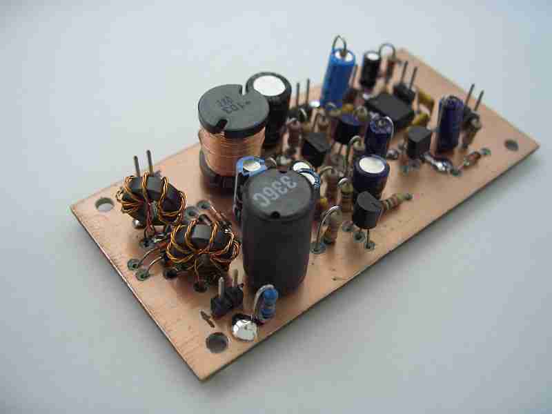
Photo 1: AF amplifier, Diplexer and Diode Ring Mixer
Current project:
DC TRX for 40/30 m for CW operation. AF section provides 110 dB voltage
gain. Best performance with high impedance headphones.
Project task:
- fun fun fun
- few (available!) parts
- suitable also for beginners
- inexpensive
- weekend project
- free of alignment
- regarding national and international regulations for transmitters and receivers
- excellent receiver data for such a design
- full bk
I don't recommend ugly construction for VFO, mixer and AF parts
of DC receivers because of increased microphony effects. I
recommend instead a solid PCB design with a double sided PCB with one
side routed and the other serves as a ground plane.
PCB Service: I have PCB layout for EAGLE available (single side routed).
After test period I will publish PCB data (format .brd for EAGLE PCB layout software) here. If you can't wait then you are encouraged to ask for the layout via e-mail:
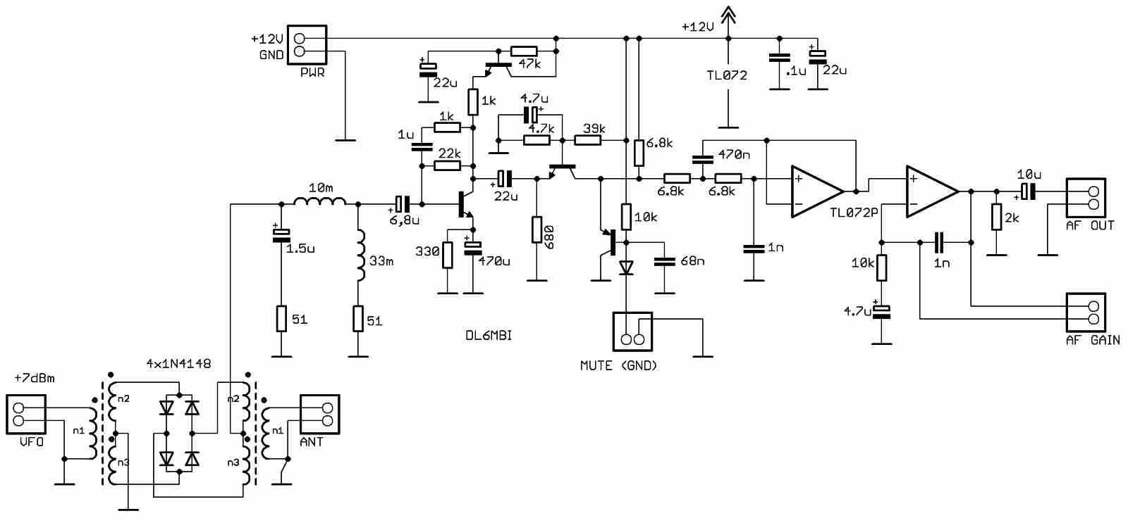
Circuit diagram:

1. Mixer
A doubly balanced diode ring mixer is used. RF input power: approx. > +7 dBm.
Mixer Transformers:
T1=T2 5 turns trifilar 0,22mm on FT37-43
Ready available mixer design will be available later (TUF-1, SBL-1 etc...).
2. Diplexer
Broadband matched to about 50 ohms. Peak at approx. 750 Hz. Inductors are available from RS Components or other sources.
Diplexer Inductors:
10 mH: RS Components No. 675-5333
33 mH: RS Components No. 715-7276
3. First AF stage
A MPS2222A is
used here. Matched to about 50 ohms input/output impedance. About 20 dB
gain. Lower noise level possible with another transistor (e.g. BC547B,
2N4124). Active voltage decoupler inserted to prevent hum.
4. Second AF stage
Emitter coupled audio stage with impedance transformer option. MPS2222A. About 20 dB gain. Output is muted with T3 (2N3906)
5. Third AF stage
OP 1 of TL072 dual-operational amplifier.
750 Hz CW Filter. Change 1nF capacitor for center frequency change.
6. Last AF stage
OP 2 of TL072. Variable gain
amplifier. Best performance with high impedance headphones. Low
impedance headphones allowed (humming may be observed).
Connect a 100 kOhm variable resistor to "AF Gain" port.
Current Status/Bugs:
- VFO testing
- Receiver runs very well
- Mute clicking

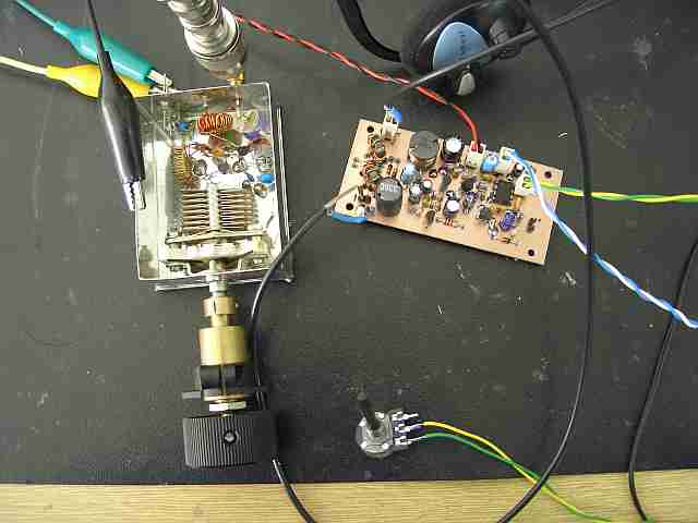
Photo 2: Current status of development
To prevent hum:
- terminate all mixer ports with impedance ~ 50 ohms !!!
- shield VFO
- prevent ground loops especially at the headphone port. Keep headphone plug earth-free when possible
- use power supply with good hum suppression
Project will be continued.
March, 23rd 2011
DL6MBI
Next to come:
- 40m VFO
- PA class C
- TX filter
- Pre-Selector
- RX/TX switching unit
<<< home


