Best results are obtained with low impedance sources. With DC receiver Type 002 a suitable point for decoupling is at the end of the tschebycheff bandpass filter 0.5-1.5 kHz, at the emitter of transistor T4 (a decoupling capacitor of several microfarads is necessary).
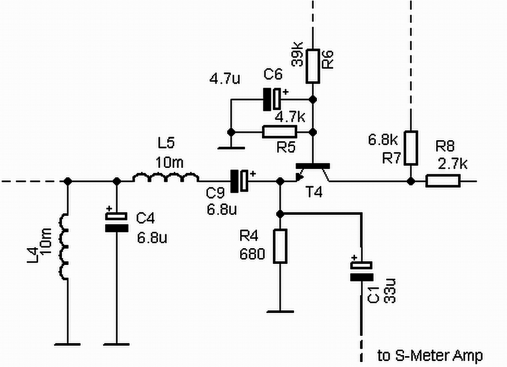
Picture: Decoupling of the AF signal to the S-Meter amplifier via capacitor C1 (see DC Receiver Type 002)
The SA614 logarithmic amplifier is available from several sources. One source is RS Components. Google it!
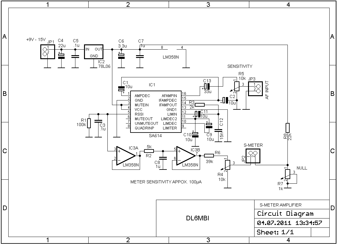
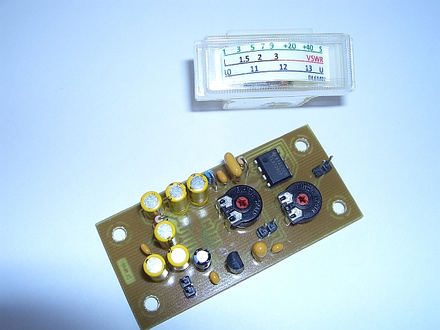
The SA614 is a SMD part. It is mounted at the bottom side of the circuit board. The picture shows a TL072 dual-opamp, although in the meanwhile I substituted it to a LM358 because of the single source circuit. I use a 100µA meter as a indicator. The user is obliged to resample the output resistor network for suitable output current. With no input signal a output current of a few microamperes remains. The meter needle is therefore not exactly at "zero". If you want maximum readout accuracy you need to compensate this remaining current by proper selcting R4; R6, R7, R8. The suggested resistor network in the circuit diagram is suitable for a 100µA instrument.
The instrument I used is from German distributor Bürklin (www.buerklin.com).
Part# 16K210
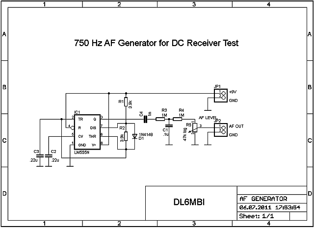
I printed a s-meter scale to a simple printer after I measured the signalstrengh. If you don't have a signal generator for calibration I recommend to use a homemade signal generator made of a NE555 signal generator and a variable resistor. The frequency should be tuned to about approx. 750 Hz.